With so much data being thrown at our eyeballs these days, it’s worryingly easy for the actually important stuff to slip by occasionally. So when [Liam Jackson] wanted a way to visualize the number of test failures popping up in the continuous integration system at work, he went with a novel but effective solution — universal motorcycle tachometers.
It turns out these little gauges can be had for under $10 a piece from the usual overseas retailers, and are very easy to drive with a microcontroller. As [Liam] explains, all you need to do other than providing them with 12 volts, is feed them a PWM signal. Even though the gauges are designed for a 12 V system, they apparently don’t have any problem responding to the 5 V logic level from the Arduino’s pins.
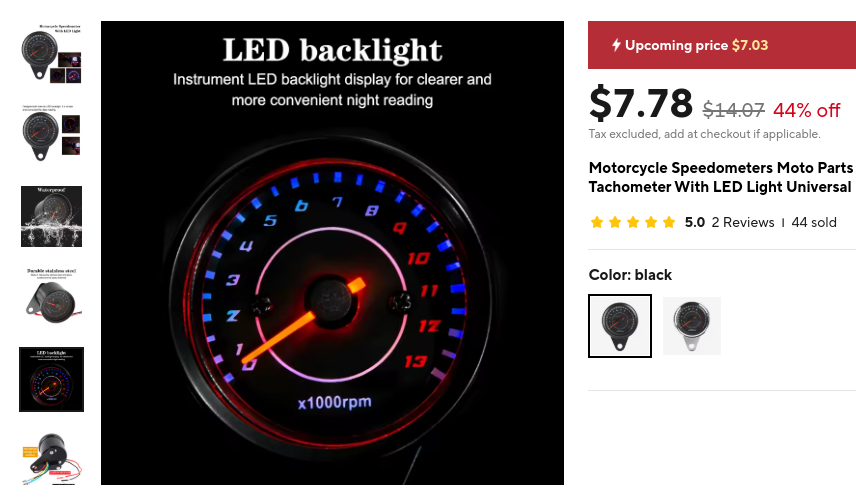 As for the frequency he says that 1,000 RPM corresponds to 16.66 Hz, so you can just multiply up from there to show whatever number you wish. That said, [Liam] warns that the gauges draw several hundred milliamps once the needle gets into the two digit range, so keep that in mind. Conveniently, those number happen to be in red anyway…
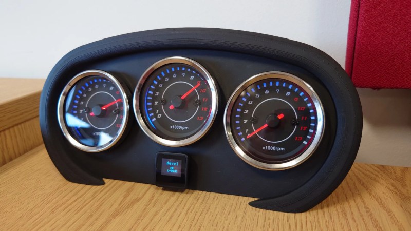
For his particular application, [Liam] put three of the gauges together to create a very handsome dashboard. If you want to recreate his setup exactly he’s made the STLs available for the gauge cluster housing. Note the small OLED at the center, this offers a way to show a bit more context than the three analog gauges alone can express, especially if you’ve got an application where you might be switching between multiple data sources.
Over the years we’ve seen several projects that repurposed analog gauges of various types, often for showing computer performance, but they generally involved having to drive the galvanometers directly. That these tachometers can simply be fed a simple digital signal should make implementing them into your project much easier.


Quote: “[…] when displaying high numbers (e.g., 9 or 10), the dials can each draw several hundred milliamps from the 5V source […]”
Is this because the gauges have a return spring mechanism and going to higher numbers equals a higher force that is working against the motors? Or is this some other mechanism? Not an issue for ICE vehicles of course, but if you want to minimize energy consumption, stepper motors should be put in these gauges.
Most gauges use the X27.168 stepper motor, so power usage shouldn’t change.
Maybe someone found some servo thingy that was a cent cheaper even if it needs a spring. Since they’re cheap I might buy a few just for curiosity sake. The junk pile isn’t full yet.
Yes I think it is working against a spring, but maybe behind a gearing because it returns slowly to 0 after removing the power.
I would’ve liked to have seen if it was possible to drive the motor directly, but unfortunately you cannot take these apart without sawing the case apart or bending the metal ring around the glass.
Ultimately a few hundred ma at 5v when displaying non-zero values isn’t too bad, and I have the dials go into standby when the office is empty.
Nice hack!
Oh, this brings back memories. Back in the 80s, a friend had a little MG sports car. The tach died, he was quoted an astronomical sum by the dealer for a new one. So, I disassembled it and found a Texas Instruments chip. I was working as an engineer, so I called my TI rep and asked for a replacement chip, only to find out that it was a custom for the tach maker. Not to worry, they had gone and looked in a colleague’s desk, found one, and were mailing it out to me!
I saw him a few months ago. He still has the car, and the tach is still working :-)
Cool story bro!
B^)
Nothing wrong with the build, but failing tests in a CI pipeline should not need a dial. If there are more than 0 failing tests then you should be fixing them. Whether there’s 1 or 10 shouldn’t make a difference.
I made a gauge like that about 4 years back, but i used a addressable led ring, but they were operational tests, not build or fuzz testing.
The Julia program was run before and after the tests, which read the generated JSON file for the results and send them to an arduino board to show the FAIL/SUCCESS ratio, and a random animation while the tests were running. It was fun.
I think i might use this motor cycle gauge in the future, i like a this sort of gauge aesthetically better than a led ring, but it kind of sucks you can’t easily change the background. You have to hacksaw it open from the side, like i had to do to an automotive gauge, which didn’t work.
Side note: it’s not PWM the gauge eats, it’s PFM.
The original blog mentions these dials are for a very large matrix of very long running integration and system test suites that would not be feasible to run on each branch.
I guess calling them CI is not quite right. But it’s the easiest way to get across the concept of what they are for without going into the detail of our various test suites and infrastructure!
Seems they would work on pulse frequency rather than PWM. The pulse frequency would rise as engine RPM increases, as electronic tachs were traditionally fed from primary ignition pulses. I might be out of date!
From the write up it’s clear that this is actually how they work, since nowhere does it mention duty cycle, only frequency…
Wellcome to HaD QoS.
Yes that is true but I used the “Slow PWM” Arduino library to drive them. You can just give it a frequency and the duty cycle didn’t matter much!
Yup, 1000 RPM == 16.6666 rev./sec, so with 1000 RPM == 16.6666 Hz, the gauges are expecting one pulse per crankshaft revolution. The linked article says the gauges expect the signal from a single-cylinder engine’s spark plug, but that’s only true for a two-stroke engine (granted, common in older motorcycles.)
Nailed it!