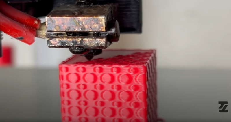
Just when you think you’ve learned all the latest 3D printing tricks, [TenTech] shows up with an update to their Fuzzyficator post-processing script. This time, the GPL v3 licensed program has gained early support for “paint-on” textures.
Fuzzyficator works as a plugin to OrcaSlicer, Bambu Studio, and PrusaSlicer. The process starts with an image that acts as a displacement map. Displacement map pixel colors represent how much each point on the print surface will be moved from its original position. Load the displacement map into Fuzzyficator, and you can paint the pattern on the surface right in the slicer.
This is just a proof of concept though, as [TenTech] is quick to point out. There are still some bugs to be worked out. Since the modifications are made to the G-code file rather than the model, the software has a hard time figuring out if the pattern should be pressed into the print, or lifted above the base surface. Rounded surfaces can cause the pattern to deform to fit the surface.
If you’d like to take the process into your own hands, we’ve previously shown how Blender can be used to add textures to your 3D prints.


Wouldn’t the surface() operator in OpenSCAD do pretty much the same thing? Except the result would be in the .stl file and not need any mods to the gcode. I suppose it would only work on flat surfaces, though.
You can apply various transforms to surface() in openscad, but it is computationally and memory intensive – and openscad is not exactly known for speed in the first place. There’s an alternative renderer (Manifold? maybe) that is a massive speedup, but you’ll need a recent-ish dev build. And also you will need to increase the CGAL cache size.
Can I use that as a plugin in PrusaSlicer?
Literally said it I’m the article.
TenTech has a lot of great ideas, but they’re truly shooting themselves in the foot by implementing them as post-process scripts. This (and bricklayer, and smoothificator) would work a lot better by being implemented directly into the slicer.
Well, maybe not.
I wonder if you could “tattoo” patterns upon injection mold model parts—like the Motion Picture Enterprise refit—only now can the pearlescent sheen be captured:
https://techxplore.com/news/2025-01-scientists-digitally-iridescent-bird-feathers.html
Thank you. I implement that stuff as postprocessing scripts because it is simply the fastest way to get a proof of concept out to the public. I agree with you that it would better be implemented in the slicers. But with postprocessing scripts, people can easily test these things to see wether it’s worth to implement.
Hey TenTech!
Sorry for wasting your time, but how would one (me) have to start to do something like you did.
My questions:
-Why didn’t you change the model via displacement in blender? (two clicks, also scriptable)
-Why didn’t you use blender as a scripting platform for this? (python support)
-Does it only work in vase mode?
-If I get this correctly, I would need to manipulate the already existing g-code coordinates to a new position to make the new mesh? So the number of G-Code commands wouldn’t change? Or is the script adding points to compensate for the bigger circumference?
So my steps would be:
0. read and find out if slicer prints perimeters or infill first
1. read a given number of gcodes, or even better until layer change or large travel moves
2. build closed loops from coordinates
3. get normal-vector of each gcode coordinate
4. read displacement map
5. read UV-map to know where to put the texture (is it even possible to use UVs? if not, how do you do it?)
6. assign displacement to gcode coordinates
7. calculate new coordinate with this displacement to replace gcode coordinates
8. write changes
9.Proceed with step 1.
Am I even close?
Thank you for your work!
P.S. I read somewhere, that Cura, Prusa, etc. have a preference for perimeter printing directions. Outer perimeters usually print counter-clockwise. Inner perimeters get usually printed clockwise. Perhaps this helps with identifying in-/outside.
SB
Writing a gcode post-processing script is much easier than figuring out and modifying slicer code
Is it? Finding your way in a jumbled mess of machine generated strings And keeping track of the location where you are and then creating more… You would(should!) not actually be modifying slicer code either, since the slicer is created to be good at “slicing” and the goal here is to modify the expected result, aka the model.
For the scripts he has implemented, yes it is indeed much faster and easier to work with the gcode (speaking from experience).
This has been available for ages (years and years) in the ideamaker slicer. It works great.
I’m gonna side with the comments suggesting that this shouldn’t be a post-processing script.
I think the best option here would be a good premade setup for Blender. IIRC it can easily apply textures and map those to model offsets.
Working on the model directly is better for this than after sloving and this should be more flexible than the OpenSCAD command.
Disagree. This gives nice flexibility for testing and personally i like it that i can do it for any printable model much without firing up the modeller and trying to work with gazillion vertices.
As for this being a feature in the slicer, sure that’d be better and maybe at some point some slicer will implement it.
I’m sure Blender and other modelling software already has this sort of thing.
I’m pretty sure you can work with it the same way the plugin works in Blender. It’s not like you need millions of verts and to sculpt it by hand.
It has texture painting and a robust system that could deform the mesh procedurally.
So you just slap the smilie face on the cube like the example and use it for masking on the displacement.
I just used blender and gimp. One of my favorites was taking pictures of the stonework from medieval castles and displacing it on super simple geometry and effectively made a castle play set for my toddler (at the time). Turning down the minimum segment in slicer helped give some really nice rock texture.
That’s pointed out specifically at the end of the post, “If you’d like to take the process into your own hands, we’ve previously shown how Blender can be used to add textures to your 3D prints” – and this in turn links to a video on YouTube showing exactly how to do that within Blender.
its just the principle of Zbrush … and already does it in it and export stl for years
If you got a bit clever you could also print the top layers of the cube shown and possibly the bottom ones with a different colour as well just using gcode pause commands if you arent a multi colour user.