To the extent that you’re familiar with magnetostriction, you probably know that it’s what makes big transformers hum, or that it’s what tips you off if you happen to walk out of a store without paying for something. But magnetostriction has other uses, too, such as in this clever linear position sensor.
Magnetostriction is just the tendency for magnetic materials to change size or shape slightly while undergoing magnetization, thanks to the tiny magnetic domains shifting within the material while they’re aligning. [Florian B.]’s sensor uses a side effect of magnetostriction known as the Wiedenmann effect, which causes a wire to experience a twisting force if a current pulse is applied to it in a magnetic field. When the current pulse is turned off, a mechanical wave travels along the wire to a coil, creating a signal. The difference in time between sending the pulse and receiving the reflection can be used to calculate the position of the magnet along the wire.
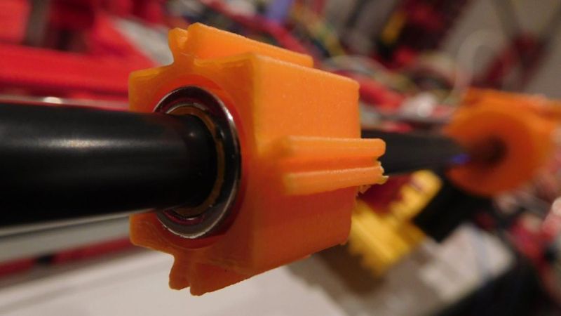
To turn that principle into a practical linear sensor, [Florian B.] used nickel wire stretched tightly down the middle of a PVC tube. At one end is a coil of copper magnet wire, while the other end has a damper to prevent reflections. Around the tube is a ring-shaped cursor magnet, which can move up and down the tube. An exciter circuit applies the current pulse to the wire, and an oscilloscope is used to receive the signal from the wire.
This project still appears to be in the prototype phase, as evidenced by the Fischertechnik test rig. [Florian] has been working on the exciter circuit most recently, but he’s done quite a bit of work on optimizing the cursor magnet and the coil configuration, as well as designs for the signal amplifier. It’s a pretty neat project, and we’re looking forward to updates.
If you need a deeper dive into magnetostriction, [Ben Krasnow] points the way.


Everything old is new again. The Summagraphics tablets made in the 1980s uses this principle, in two dimensions. Actually, it had a set of parallel nickel ribbons stretched one direction, and it used the magnetorestriction principle for only one axis (don’t remember which). The other axis position was determined by interpolation between the signals received from pulsing successive ribbons. The one I had used a handheld “puck” with four buttons, that had about a 1/2″ coil, which could detect the position up to about 1/2″ above the tablet, and there was also a pen and a 16-button puck available.
That’s a pretty amazing solution, how do you even remember such a thing? Certainly older than my (also incredibly old by now) Wacom tablet. Thanks for sharing
I remember those, at least I think I do, I remember a tablet with a pick that had a clear perspex bit with cross hairs and a visible coil?
I think what’s new about this is the application by a hobbyist though I’m sure there’ll be someone along in a minute with a dozen examples of other hobbyist projects all over the web.
Yes, that’s it exactly. I worked for a company that made IC design workstations, and we had some models that used the Summagraphics tablets (which I had to learn how to rewind coils on, since if you dropped the puck on the floor the coil was likely to pop out, breaking the wire) and one model that used a Fujitsu tablet, but that used capacitive sensing. I think the Fujitsu tablet was used on the flagship model because it had higher resolution.
Yes, what’s old is now new again. To my memory magnetostictive linear position sensors have been used in industry for at least 40 years. The brand Temposonics comes to mind but I am sure there are others. Magnetostrictive sensors were rugged, reliable, and accurate. They were often used in critical applications like boiler feedwater tank level measurement. The only downside I remember is that they were a little pricey and had to be custom ordered with the specific length of sensor probe required, but that could be over 10 metres.
I was a little confused at first because I’ve used before. They are often used in hydraulic cylinders, which is where I was first introduced to them. It may be an old technology but someone is at least trying to reproduce it in an open environment. When I was using them they were not available within the budget of a hobbyist.
That’s the point of this project! It’s a common industry measurement principle. Making one work on the hobby level was the goal. And it look pretty good to me.
Would ordinary constantan or nichrome wire work, or do you need some special magnetostrictive wire?
Ni wire works as well as NiFe for heaters (e.g. NeFe30 awg21). With Fe wire from a local hardware store I had no luck. I did not try Constantan nor nichrome. I assume they won’t work.
I don’t think it’s a special alloy; I think it’s just a nickel ribbon. As for nickel alloys, it ought to be worth a try!
Also, keep in mind that this works because the wire provides an acoustic delay line, allowing the time delay between to be easily measured, so even though magnetostriction is used here, it should also be possible to pick up a pulse induced by a coil at one end of a steel wire, with a coil on the moving part picking it up. This is much the way electric guitar pickups generally work, except that they use a permanent magnet to magnetize the string, then pick up the change in reluctance as the string’s distance from the pickup changes. So maybe if you want to stay away from exotic materials, you could try different gauges of guitar strings, including copper- or bronze-wound ones.
Yes, but the magnetic propagates much faster (close the speed of light) through the material. So, it is much more difficult to build the electronics needed to measure the time difference accurately enough.
The point of magnetostrictive materials is that the change in shape (acoustic wave) is accompanied with a change in magnetic field, so the acoustic torsion wave that is traveling along the wire can be detected by the magnetic field it is carrying along. The magnetic field is moving at the speed of the mechanical wave.
If you want to use other materials like copper wire, you must supply a continuous current to maintain the magnetic field around the wire, to detect the motion of the wire. Any old wire will jump transversely against the magnet when the current is switched on, and that sets off a transverse acoustic wave.
The only problem is, the velocity of a transverse wave along a wire depends on the tension of the wire, so it’s not a constant you can rely on. It’s a parameter you have to tune, and keep re-tuning as your mechanical setup settles down, like having to re-tune a guitar every time you start playing it.
Torsional waves in the wire don’t depend on the tension of the wire, at least if the wire is very thin relative to its length. In that case, the propagation speed of the wave depends on the cross section of the wire and its mass density, which eliminates the effect of the mechanical setup and diminishes the effect of temperature.
The fact that the magnetic field in the example device is set sideways to the wire is alarming, because it implies a transverse instead of a torsional wave, so the description of it is faulty and the whole setup is highly likely to drift around and produce unreliable readings over time.
magnetic field it is carrying along. The magnetic field is moving at the speed of the mechanical wave.
Sure about that?
It’s not necessary to “move” the magnetic field. It’s the acoustic energy that propagates down the wire, not the magnetic field. The wire torsional movement when it enters the pickup induces the signal.
The torsion wave in my setup travels with a speed of 3030 m/s.
The creation of the torsion wave is caused by the Wiedemann effect,
and the change of the magnetic permeability by the torsion wave – which induces the sighal – is caused by another effect (I thing it is called Mateucci effect).
I butt soldered a piece of copper wire with same diameter between Ni wire pieces:
with Coil in copper region I cannot measure a signal, but with the Coil at the other side a signal (weaker) can be detected. So the torsion wave is transmitted over the copper wire and magnetic properties are important to get a signal. Perhaps a measurement with guitar pick-up would work.
Magnet field direction: radial field is originally suggested (patent of J. Tellermann) but a radial field obviously works too. The signal speeds are the same. If transversal waves would be activated I would expect different speeds.
Indeed, when wire is attracted to the magnet and hits the wall of the tube signal can be quenched or additional signals can occur. Free wire experiments are easier in that respect. For tubed version protecting the wire in the center region with rubber rings, toilet paper etc. helps to avoid this.
A magnetic pickup that is co-axial to the wire cannot detect a torsional wave. If you simply twist the wire, nothing in the magnetic configuration changes, so there’s no induced current.
The mechanical acoustic torsion wave in the wire involves shear stress, and stress on a magnetostrictive material either causes a difference in the magnetic properties of the material, or it causes a magnetic field to appear at the point of stress due to the alignment of magnetic domains in the material. In other words, the magnetic ripple you’re picking up with the coil is caused by the mechanical ripple in the wire, and is essentially moving at the speed of sound, not at the speed of light.