In an ideal world, devoid of pesky details like contact resistance and manufacturing imperfections, you would be able to double the current that can be provided to a device by doubling the number of conductors without altering the device’s circuitry, as each conductor would carry the exact same amount of current as its neighbors. Since we do not actually live inside a simplified physics question’s scenario, multi-wire powering of devices comes with a range of headaches, succinctly summarized in the well-known rule that electricity always seeks the path of least resistance.
As recently shown by NVidia with their newly released RTX 50-series graphics cards, failure to provide current balancing between said different conductors will quickly turn it into a practical physics demonstration of this rule. Initially pinned down as an issue with the new-ish 12VHPWR connector that was supposed to replace the 6-pin and 8-pin PCIe power connectors, it turns out that a lack of current balancing is plaguing NVidia GPUs, with predictably melty results when combined with low safety margins.
So what exactly changed that caused what seems to be a new problem, and why do you want multi-wire, multi-phase current balancing in your life when pumping hundreds of watts through copper wiring inside your PC?
Resistance Is Not Futile
In the absence of cheap room-temperature superconducting wires, we have to treat each conductor as a combination of a resistor, inductor and capacitor. These parameters set limitations on properties such as how much current a conductor can carry without changing phase from solid to gaseous. The contact resistance between the conductors of both sides in a connector adds another variable here, especially when a connector wears out or the contacts become corroded.
In the case of the 6-pin and 8-pin PCIe power connector, these are based on the Molex Mini-Fit series, with the commonly used Mini-Fit Plus HCS (high current system) rated for 100 mating cycles in tin plating or 250 cycles in gold, and a current rating of 8.5 A to 10 A per pin depending on whether 18 AWG or 16 AWG wire is used. The much smaller connector of the 12-pin 12VHPWR, and equivalent 12V-2×6, standard is rated for only 30 mating cycles, and 9.5 A per pin. It is based on the Molex Micro-Fit+ connector.
The smaller pin size and lower endurance increases the possibility of poor contact, as first demonstrated with the 12VHPWR connector back in 2022 when NVidia RTX 40-series cards experienced run-away thermal events where this power connector on the GPU side melted. Subsequent research by the team at Gamers Nexus showed this to be due to poor contact within the connector with resulting high resistance and thus a massive thermal hot spot. Following this event, the 12V-2×6 update to 12VHPWR increased the length of the power pins and decreased that of the four sense pins.
The idea behind this change is that by extending the length of the power and ground pins by 0.25 mm and shortening the sense pins by 1.5 mm there’s a higher chance of there being an actual good contact on the ground and power pins when the sense lines signal the GPU that it can start drawing hundreds of watts.
This change did only affect the male side of the connector, and not the cable itself. This made it very surprising to some when after the much higher wattage RTX 5090 GPUs were released and suddenly cables began burning up,with clear melting visible on the GPU and power supply side. What was going on here?
Multi-Phase Balance
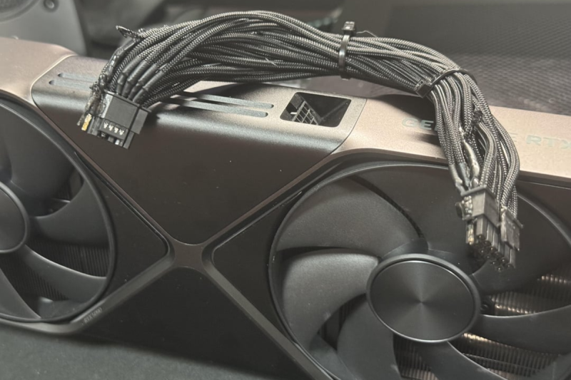
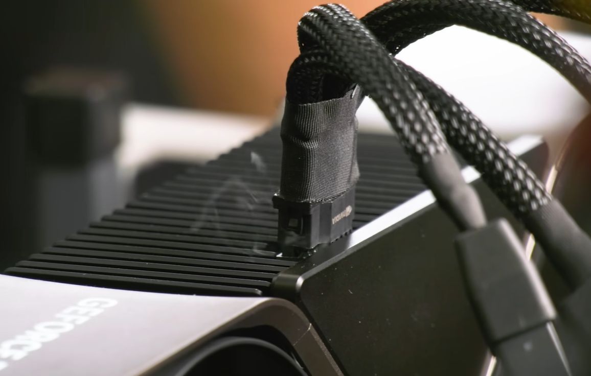
Shortly after the first melting cable event involving an RTX 5090 Founders Edition (FE) GPU popped up on the internet, Roman [Der8auer] Hartung reached out to this lucky person and – since both live quite close – borrowed the damaged GPU, PSU and cable for an investigative video. Involved were not only an RTX 5090 FE GPU, but also the PSU with its 12VHPWR connector. On each side the plastic around one pin was completely melted, with the cable having to be forcibly removed.
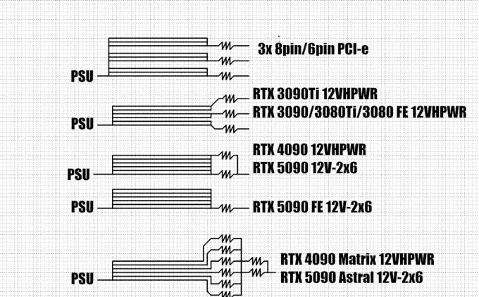
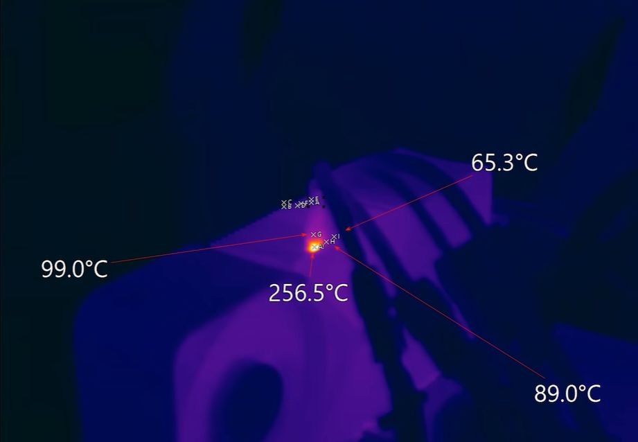
During Roman’s testing with another RTX 5090 FE and 12VHPWR cable he found that two of the six 12V wires were significantly warmer than the rest, courtesy of these carrying over 22 A versus around 2 A for the others while the PSU-side connector side hit a blistering 150 °C. This result was replicated by some and seems to be fully due to how the NVidia RTX 5090 FE card handles the incoming power, by tying all incoming power lines together. This is a practice that began with the RTX 4090, but the RTX 5090 is the first to pull close to the rated 600 watts of the 12VHPWR/12V-2×6 connector. This was explained quite comprehensively in a comparison video by Buildzoid.
Because with the RTX 4090 and 5090 FE GPUs – as well as some GPUs by third-party manufacturers – these 12V lines are treated as a singular line, it is essential that the resistance on these lines is matched quite closely. If this is not the case, then physics does what it’s supposed to and the wires with the lowest resistance carry the most current. Because the 12V-2×6 connector on the GPU side sees only happy sense pins, it assumes that everything is fine and will pull 575 watts, or more, through a single 16 AWG wire if need be.
Meanwhile the Asus RTX 5090 Astral GPU does have individual shunt resistors to measure the current on the individual 12V lines, but no features to balance current or throttle/shutdown the GPU to prevent damage. This is actually a feature that used to be quite common, as demonstrated by this EVGA RTX 3090 Ti GPU:
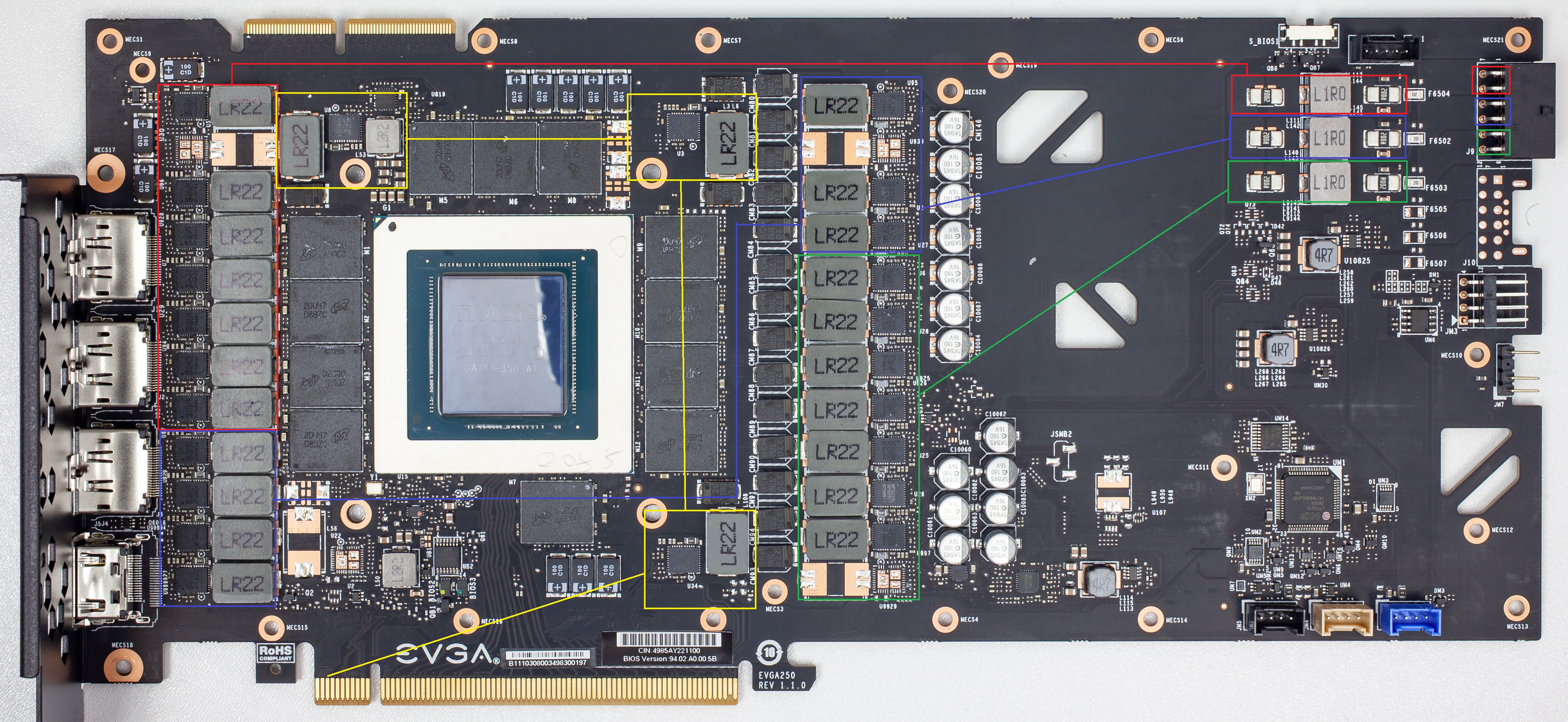
On the top right the triple sense resistors (shunts) are visible, each of which is followed by its own filter coil and feeding its own set of power phases, marked in either red, green or blue. The yellow phases are for the RAM, and are fed from the PCIe slot’s 75 Watt. The bottom right controller controls the phases and based on the measured currents can balance the current per channel by shifting the load between parts of the phases.
This is a design that is completely omitted in the RTX 5090 FE design, which – as Igor Wallossek at Igor’s Lab describes it – has been minimized to the point where crucial parts have begun to be omitted. He also covers an MSI RTX 3090 Ti Suprim card which does a similar kind of phase balancing before the RTX 4090 and RTX 5090 versions of MSI’s GPUs begin to shed such features as well. It would seem that even as power demands by GPUs have increased, crucial safety features such as current balancing have been sacrificed. As it turns out, safety margins have also been sacrificed along with these features.
Safety Margins
The ugly truth about the switch from 8-pin PCIe connectors to 12-pin 12VHPWR connectors is that while the former is rated officially for 150 watts, this power level would be hit easily even by the cheapest implementation using crummy 18 AWG wiring. With the HCS connectors and 16 AWG wiring, you are looking at 10 A × 12 V × 3 = 360 watts, or a safety margin of 2.4. With cheaper connectors and a maximum of 7 A per wire it would still be a safety margin of 1.68.
Meanwhile, the 12VHPWR/12V-2×6 with the required 16 AWG wiring is rated for 9.5 A × 12 V × 6 = 684 watts, or a safety margin of 1.14. In a situation where one or more wires suddenly decide to become higher-resistance paths this means that the remaining wires have to pick up the slack, which in the case of a 575 watt RTX 5090 GPU means overloading these wires.
Meanwhile a 8-pin PCIe connector would be somewhat unhappy in this case and show elevated temperatures, but worst case even a single wire could carry 150 watts and be happier than the case demonstrated by [Der8auer] where two 12V-2×6 connector wires were forced to carry 260 watts each for the exact same wire gauge.
This is also the reason why [Der8auer]’s Corsair PSU 12V-2×6 cable is provided with two 8-pin PCIe-style connectors on the PSU side. Each of these is rated at 300 watts by Corsair, with Corsair PSU designer Jon Gerow, of JonnyGuru PSU review fame, going over the details on his personal site for the HCS connectors. As it turns out, two 8-pin PCIe connectors are an easy match for a ‘600 watt’ 12VHPWR connector, with over 680 watt available within margins.
There’s a good chance that this was the reason why [Der8auer]’s PSU and cable did not melt, even though it clearly really wanted to do so.
Balance Is Everything
Although it is doubtful that we have seen the last of this GPU power connector saga, it is telling that so far only GPUs with NVidia chips have gone full-in on the 12VHPWR/12V-2×6 connectors, no doubt also because the reference boards provided to board partners come with these connectors. Over in the Intel and AMD GPU camps there’s not even a tepid push for a change from PCIe power connectors, with so far just one still-to-be-released AMD GPU featuring the connector.
That said, the connector itself is not terrible by itself, with Jon Gerow making the case here quite clearly too. It’s simply a very fiddly and somewhat fragile connector that’s being pushed far beyond its specifications by PCI-SIG. Along the way it has also made it painfully clear that current balancing features which used to exist on GPUs have been quietly dropped for a few years now.
Obviously, adding multiple shunts and associated monitoring and phase balancing is not the easiest task, and will eat up a chunk of board real-estate while boosting BOM size. But as we can see, it can also prevent a lot of bad publicity and melting parts. Even if things should work fine without it – and they usually will – eating into safety margins and cutting components tends to be one of those things that will absolutely backfire in a spectacular fashion that should surprise absolutely nobody.
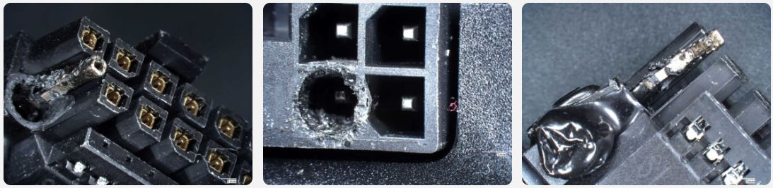
Featured image: [ivan6953]’s burnt cables.


Maybe UL-listing-style requirements need to be applied to field-exhangeable internal DC components if they’re going to draw crazy currents like that.
Typically, a component is not ‘listed’.
There is NRTL recognition of these molex component connectors. But the end-use of recognized components must be per the Conditions of Acceptability found in the NRTL report. Most NRTLs provide ratings and model numbers of listed and recognized items.
A test report by Underwrites Labs, or any other NRTL, does not provide any assurance other than that the manufacturer submitted a sample product to the test lab. Regardless of any FUS audits, once a product goes into production, it is up the the designer and manufacturer of the end-use item to verify that the construction and materials are safe for the rated operating conditions.
In the long run, UL, CSA, TUV, ETL, or any other test mark do not indicate diddly squat. There is no magical protection provided by a UL mark.
I keep hearing people say this.
Here’s my experience. I was managing installation of a high temperature operational life burn-in oven that was UL listed. When we put it in, we needed (for insurance) documentation of the UL certification, and a guy who worked directly for Underwriter Laboratories flew out, came to our site, took the machine partly apart (removed safety covers and disassembled the power supply EMI cover) to specifically inspect several parts that had revised designs because of a previous design problem, to verify that the modifications had been done. He then put everything back together, we powered the system up and made sure it was functional, and at that point he certified that it had been inspected by putting a UL label on it that had a serial number unique to that label, and printed out a certification and signed it.
So having a UL mark can have significant meaning, depending on what’s being done, under some circumstances.
Reminds me of the better business bureau. Businesses just pay to use the logo but it doesn’t really offer consumer protection.
They are the original AngiesList…
AngiesList stole their business model from the BBB.
Just like Tata consulting stole theirs from EDS.
bbb still carries weight. or at least last time a big box store tried to screw me which was a couple years ago. had to send them after newegg once because they sent a partial order, charged for the full order and refused to acknowledge that i didn’t get the rest of the order.
BBB is useless. Had an issue with a company that they failed to resolve over the course of several months, then they basically ghosted me. Reported to bBB and they were basically like “well we reached out but they didn’t respond so oh well”.
As recently demonstrated by NVIDIA with the introduction of their latest RTX 50 series graphics cards, which offer significant advancements in performance and efficiency, users can expect enhanced graphics capabilities and improved support for the latest gaming and creative applications.
F off useless spam bot
All of this is a lie, 50 series did not improve efficiency, nor have a significant increase in performance.
The increase in efficiency and performance completely depends upon the graphics card being replaced by the 5090.
In my humble opinion I would just add more power connectors until I were happy with the margins.
Use a big fat (keyed) IEC cable/connector to deliver the 12VDC rail and be done with it, it’d be cheaper as they already exist and are mass produced. put the connector on the back if you care how it looks. NVIDIA cheaping out, doubling down on using a shit wafer thin tinfoil connectors with as few strands of copper as possible, and pretending it’s the users fault for not plugging it in right, put the efforts of their army of engineers who worked on these chips, cooling solutions, firmware and drivers to waste.
IEC cables are only rated to 16 A typically, which would be only 200 W at 12 V.
Just slap a 175A Andersen connector on the thing and call it done.
Those Anderson connectors are no joke, I switched my bike over to one of those when I went 80v, and it’s the coolest spot in the power cable. I occasionally have to redo the splice to the motor controller because they melt (which is fine, I’d rather that happen than hurt the motor), but the connector doesn’t even get warm. I’m not sure what the smallest Anderson connector is rated at but it’s likely much more than a 5090. Your idea is a good one, but I can hear the enthusiasts crying about their aesthetics already.
Maybe it would be better to provide a 36v-48v rail on ATX power supplies since then less current would be needed to supply the same power.
Then you need to add step-down converters on the card itself to drop voltage from said 36V-48V all the way down to logic voltage levels used by GPU (5V to 0.6V). That brings the GPU price up, makes it bigger and adds more heat to deal with on the GPU side.
It is almost certain that there are already step-down converters. All those gray monoliths in the board photo (ones labelled LR22 and L1R0 for example) are inductors that are part of a buck converter circuit. The suggestion to put much higher voltage to the card is a good one, and it’s likely to be coming at some point.
How do you think the GPU derives that 0.6V from 12V?
resistance in the power plug duh
LMAO
Yeah, thanks for making me giggle like an idiot while sitting in a boring meeting :D
A switching regulator with a higher ratio between input and output voltage tends to see lower efficiency.
A random example. LTC1265 regulator reference circuit at a certain constant load. Vin = 6 Volts – 95%. Vin = 12 Volts – 87%
It also gets more expensive to build a switching regulator capable of dealing with 48 Volts, because of the voltage handling requirements of the components and the greater transients that need to be suppressed. It’s much more economical to do the majority of the voltage drop in bulk with a big power supply than a bunch of small ones.
My point exactly. Might have not been descriptive enough in initial post. I would assume that in current designs there is stepped conversion happening (like 12V to 5V to 3.3V to VCores). Even assuming efficiency of stepping down voltage from 48V to 12V at about 95%, the losses at 500W are going to be around 25W. That’s additional heat that you have to remove, PCB real estate to fit another block of step down regulators, etc. The way more economical and practical solution would be to actually go back to activiely measuring and balancing current per wire, that was done with earlier cards.
Then there are some safety rules in place – I’m not sure if they apply anymore – but at some point there was a rule that a single low voltage output in a PC power supply could not carry more than 250 Volt-amps because in the case of a short circuit it would present a fire risk. Hence why 20 Amps at 12 volts was the maximum you could get out of a single “rail”.
Not being able to draw all the power from a single rail means you should do load balancing anyways. If you simply tie the rails to a single point at the end, you’re defeating the point of the current limiting circuitry in the PSU and assuming that the load is balanced equally at the PSU’s end, which risks tripping the safety circuits there.
Basically, connecting multiple PSU rails together at the end of the wire is like the ring main in old UK homes, where you have two circuit protectors feeding one wire at both ends. It’s going to double the fault current needed to trip the safety because your short can be fed from both sides.
Dude half the card in the pictures is taken up with power supply components, nothing on there aside from maybe the fan is running on 12V directly.
Apparently there is already the 48VHPWR connector for that:
https://en.wikipedia.org/wiki/PCI_Express#cite_ref-PCIe5.1_CEM_43-0
The solution is to put back the monitoring systems that the 3090 had. They removed that from the 40 and 50 series and this is the result.
The joke I’ve taken to is that they should just have users run a separate AC cord for it and don’t forget to make sure it’s on a separate breaker as the PC or it’ll trip.
20v makes more sense, it is already in use for laptops and PCs with external power bricks, and could probably be pushed to 24v pretty easily.
Perhaps they should have used the fairly standardised 3.5mm banana connectors used on small brushless motors, or the 4mm banana connectors used on multimeter wiring and bigger RC motors. Those can take tens of amps each with no trouble. The connector itself would be a plastic housing (of a material rated for high temperature but never likely to actually reach it)just to keep the bunch of individual banana connectors in the right relative orientation. Fitting and removing it might take quite a lot of force, one 3.5mm connector is pretty sittf, so a whole gird would be more so. Maybe screws, like used on a VGA cable simply for securing it, could be used here to actually compresss the two banana grids together.
That would only result in a ton of fried cards and psus, as people are dumb and will plug the wrong connector in the hole if all the holes are the same shape. There is a key on 8-pin pcie that is supposed to prevent them from being inserted into the cpu 12V connectors, but people still manage the opposite and are usually lucky when their psu crowbars kick in. Having loose bullet or banana connectors floating around would also be a disaster waiting to happen. even if you put the male pins on the video card and female receptacles on cable there would still be some exposed metal. By the time you stick them in a keyed housing to prevent stupid, the connector is larger than the old 8pin that they want to get rid of because of it’s size.
Prude!
RC bullet connectors such as EC5 are keyed. So your argument is moot.
Many (all?) of the lipo connectors out there are polarized and can handle all or nearly all the power required by a 5090.
An XT60 can to 30 amps. Two can feed a whole 5090.
XT90 connectors are rated for 90 amps for applicable voltage range.
Time to break out the Anderson connectors used on forklift battery packs. /s
Imo, ATX should have moved to 24V or higher by the time USBC-PD became a thing.
That really makes no sense to me – nothing in the wide world of stuff powered by ATX actually seems to use more than 12v. If anything with the way most elements of computing have been getting more efficient dropping the 12v from future versions of the standard wouldn’t have been a shocker to me (though still some time off on that one making real sense).
Upping the voltage just for USB-PD is just daft as it already requires buck/boost functionality to turn that 5v/12v input into all the many output voltages the spec demands (and whatever voltage the brains of the outfit runs on). Plus when they seemingly inevitably decide the cables have to carry more than the already bonkers 100w in that ever upward trend to make it the powercable for all things the highest voltage is going to go up again. So should the ATX spec just skip to adding 50V pins instead?
problem is you drop the voltage you up the current, and wires are better at handling voltage than current. though i cant help but think that more voltage is not the answer. the fact that we were fine up to the point where nvidia tried to muck with the standards kinda shows where the problem lies. that’s why my last gpu purchase was an 7900xt card because i didn’t want to deal with the problem of the squid cable (especially in an sff build).
i kind of feel the same way about usb-pd. i dont like using such a fiddly connector for power.
Exactly, but as your power demand drops which modern ever increasing efficiency makes likely you can potentially drop the 12v.
Honestly I can’t find a single thing I actually like about USB-C or PD that makes me want to choose a device with that port rather than dedicated display, power, ethernet, etc. As I don’t want the device to come with just 2 ports so I have to carry around a million dongles and am SOL when the port you are using for everything and cycling so very very often breaks, or the cable I have happens not to function for this device etc.
The framework laptop is perhaps an example of how USB-C could be useful, but you can do that same concept very very easily even if USB-C doesn’t exist, it is just creating your open source module interface, that probably brings the ubiquitous USB and PCIe lanes in a rather M.2 compatible formfactor being the long established standard that means lots of ready made chips to take the voltages and I/O options already exist.
RTX 9050 FE… it’s over 9000! \o/
I don’t understand in the first place why multiple wires are used in this case that then require current balancing. Pretty much anywhere else in electrical engineering you use larger connectors with larger contact pads and thicker wiring when the current increases. For example the widely used C13/C14 vs. C19/C20 connectors.
Could someone shed some light why multiple wires are used for the 6/8 pin-PCIe and 12VHPWR connectors?
cable flexibility. its easier to bend 8 smaller gauge wires than one larger equivalent conductor. you can also fit the cables in narrower gaps if the individual wires are smaller. and you have more surface area to dissipate heat if the wires somehow get overloaded.
High strand count silicone insulated wire is very flexible. A pair of 10 AWG or even 8 AWG wires would not be hard to route in a PC case. It’s typically rated for 200°C, so it can handle a lot more heat than PVC insulated wire.
I wholeheartedly agree. Particularly when you look at power cables used for car audio amplifiers and their routing through tiny spaces. 10 AWG and 8 AWG are pretty common in this scenario.
To me this just feels like (I have zero proof) as if this is all a continuation of previous connectors. The AT mainboard connector already used multiple wires for 5V and ground. The various ATX connectors just seem to continue and extend that…
https://www.playtool.com/pages/psuconnectors/connectors.html
It’s not uncommon to do this. USB-C for example has 4 power and 4 ground pins, because it’s easier and cheaper to design a connector for a consistent pin size.
That is a solid argument, except they just did that for the 12VHPWR connector as the sense pins have a smaller footprint than the rest of the connector. But maybe there is an upper size limit for what they can manufacture with current automation…
As an EE, it seems like everyone is over-complicating what’s actually a rather simple issue. Wires are run in parallel all the time, “current balancing” is not needed. The resistance of the wires is sufficient. The problem is that you have 8 wires carrying a ton of current, and if your connector is flakey, or the user just didn’t plug it in all the way, that current can end up being carried by 1 wire. Boom, meltdown.
All this complexity with multiple shunt resistors only allows DETECTION of the problem (thus avoiding damage/fire), it doesn’t actually fix it. IMO the solution is to switch to a different connector, like an XT60. Of course the existing connector is what people already have; So the current shunt solution makes sense, as a way for the manufacturer to deal with the connector which they cannot change.
Honestly if I was the mfr, I might just slap a thermistor on there. Much simpler and accomplishes the same thing.
So what it really needs is a nice, low resistance crimped connector drawing all the rails together before going into the card?
Might as well future proof the standard, and go with 4 gauge cable and an Anderson SB connector for your graphics card.
That’s still only a kilowatt: less than a factor of two bigger than the biggest current systems.
A stock 4090Ti draws 600.
Guaranteed someone overclocked and overvolted one.
Warranty shmarranty.
The 1 pony graphics card is here.
WOOT!
Likely much less stable then stock and no faster.
Go much higher than that and it can’t be powered off 15 amp circuits in US homes. So there’s some real practical upper limits without turning the computer into an appliance in the laundry room.
Well yeah… At the basic level the current balancing is basically built into the system, when wires are parallel…
The problem is that in the real world, the individual contacts will never be identical in resistance. And when dealing with the already low resistance of wires and connector contacts, all you need is a few wires to go from basically 0ohms to 1-2ohms for things to get way out of hand.
Just 4 wires having 1.5ohms of resistance with two at 0.1ohms, means those two wires are sitting at 22A… Its not hard for crappy connector contacts to increase that small amount. I have had to deal with thin film corrosion in connectors causing issues many times. So, it’s not like this is an extremely rare phenomenon of poor connection.
And a 10% safety margin is a travesty. Even 50% is considered too low for such things. For safety critical things, like high power electricity and the potential fire hazard that brings, you would want at least 100% margin. (I am not an expert on safety margins and the general guidelines, just going by what I have picked up over the years)
This is a real problem users with little or no experience plugging high current connectors, and maybe not getting them all the way in.
This is also a sign that the discussion needs to be had on a new voltage standard for video cards something like 24 or 32V power. The One Horse Power (745.7W) video card is just around the corner.
i blame the connector myself, its a fiddly composite connector which requires complex termination and significant strain relief due to the number of wires. multiple 8-pins still works fine, at least on my 7900xt. fewer pins reduces the strain relief requirements. with gpus getting taller, there really isn’t much room inside the case to accommodate several inches of strain relief. so system builders end up crushing them to get them to fit, the 8-pin connectors are much more tolerant of this.
sense pins are a good idea, but this implementation turns a 12-pin connector into a 16-pin connector and makes the cable inflexible on both axes (8-pins wrap around better and are easier to route). two of them are just a bit code for 4 different power levels, i feel like an analog (voltage divider in the psu) or pwm signal could do this job with 1 pin (and this can be upgraded to a 1-wire serial protocol). if multiple connectors are used, then this can be implied by the number attached and this pin can be ommitted entirely. power good pin is a good idea, in that this can go out if the cable tries to draw too much power. there is also a cable present wire which seems redundant to power good.
so here is what you do, use a 10-12 pin mini connector, with 1 or 2 sense pins (this can take the place of one of the grounds since the return current is going to be less because the gpu is converting some of the wattage to waste heat). then use multiple if needed.
Current doesn’t drop under load, voltage does.
i stand corrected, idk where my brain was.
i still think the composite connector is an issue and the sense pin implementation can be reduced to 2. these could be in kitty-corner orientation at either end of the connector. if you dont get both power good and cable present then the connection is invalid. mini-10 could replace the 8-pin and keep the sense features and same power capabilities.
the other two sense pins are redundant as you can imply the capabilities of the psu by the number of gpu plugs present on the psu. because each plug has sense pins, the gpu would not power up unless both sense pins on each connector are good. 2 of them would still be needed for a 600w card. two flexible cables are better than one stiff cable.
This is a great article… I have hated this new connector since the beginning, and understood the problems it presented. But most people are not versed in electrical theory, so articles like this help.
Increasing the older 8 pin connector to 12 pin, and recertification of that for 600W would have been a better choice than to decrease the contact size. Smaller contacts have less surface area and that increases resistance.
Doing the calculations… If two wires/contacts had basically as good as connection as possible, at 0.1ohm… 2 wires were good but not perfect at 1ohm, and the last two wires were at 2ohms…
All things relative, 2ohms is not a lot of resistance. For a single wire that is basically nothing to overly concern yourself over.
But in that situation described, at 600W or 50A at 12VDC… two wires would be carrying around 22A while the other 4 would be between ~1 to 2A.
It is that easy to screw up the balancing of the power distribution of the wires. This is straight up bad engineering and circuit design. A safety margin of 10% is a travesty. A 50% safety margin is considered low and to be avoided if feasible.
It’s quite a lot actually. Three feet of AWG18 wire should have a resistance of 0.02 Ohms, which is saying that the 2 ohms is at the connection points (or your meter is off by a lot). That is the whole problem – putting even 1 Watt (1 Amp^2 x 1 Ohm) of heat in such a small contact area causes significant localized heating, and then corrosion, and then more heating as the resistance rises.
Leave it up to NVIDIA to screw up something so simple.
I wouldn’t blame Nvidia. I use the same connectors in every server and PC and have for years. Hundreds of systems running 24/7 and zero problems.
Weird it seems to only effect DIYers and amateurs and isn’t effecting the large data centers or mass deployments.
Because all the big data centers are posting on their blogs about equipment failures all the time…
idiot proofing has made the situation worse i think. they just made a better idiot. power sense pins are a good idea unless they communicate falsely that the connection is good when in fact it is not. the old 8-pin connectors were a lot more resistant to abuse, didnt require as much strain relief, and the problem of gpus getting ever larger doesn’t help much, requiring even more cable smooshing.
also datacenter hardware is significantly more robustly designed than cost cut consumer models. ive done system integration on both consumer hardware and servers and the consumer parts always had the most problems.
I had read that the data center cards don’t have power terminals wired together into a single 12v+ and a 12v- plane like the retail RTX cards. I think they’re still using distinct power zones like the 3090 was using, so even if it wants 500 W, it would be spreading that demand over specific pairs/groups of wires, not just yanking it through a single bus bar and “hoping” the load spreads out.
I strongly doubt datacenters use the same gfx card designs as your typical “enthusiast” cards.
Which is exactly the problem, as since the CryptoCurrency and subsequent machine-learning/”AI” trends, Nvidia has given less and less of a shit about said enthusiast market.
They’re only putting in about as much effort as current Microsoft is putting into making Windows not horrible to use because they can.
And AMD’s not given much of a shit about their own GPU division since Ryzen and Epyc is enabling bullying Intel who keeps on making mistakes.
The RC world figured this out already – why not use an XT-60 power connector? No need to stick with the Molex Mini-fit connector.
there are plenty of connectors that can carry the current on a single conductor, that’s not the entirety of the problem.
the female side of the connector needs to be PCB surface mountable to be efficiently manufactured. That rules out most of the “pigtail” style connectors like the XT series.
The PCB version is XT60PW, but afaik it’s not available in a reflow capable variant. Through-hole reflow would of course be appropriate and more rugged than purely surface mount parts.
There’s a 4 mm² XT60 crimp version, but with insert molded contacts, there’s no reaching around with a conventional four indent crimping tool. So one would probably need a crimping machine that can handle two cables at once (sounds like manual work), and indent both contacts at once (-> higher force).
EC5 comes to mind, but that’ll need tooling for termination as well as for seating the individual contacts in the housing.
My money is on availability of machines and tooling for automated crimping. 30 sec search says typical machines go up to 6 mm², with specialty versions supporting up to 8 mm². So 0.5-1.5 mm² conductors are probably rather convenient in terms of cost-effective mass production. Machines spit out bundles of cable segments with proper crimp terminations, ready for assembly in the housings (e.g. held in a jig, followed by automated test).
see also
“automatic terminal crimping insert housing wire harness processing machine”
https://www.youtube.com/watch?v=9um0EqVdNuA
Tail wagging the dog ;)
‘Birthing person’ side of the connector!
Yeah. Female, like he said.
Anderson SB series has PCB-wire solutions, the plastic housing clips on after soldering…
Thanks for the well researched reply. I think you’ve hit it square on.
It’s insane Nvidia charges $2-3k+ for these cards yet refuses to pay any special engineering attention to these power connectors. Surely ONE manual step as part of card manufacture can’t be out of the question, especially to mitigate a problem of their own creation.
I suspect that a lot of this is that the 800lb gorilla in GPU chip sales is no longer the desktop gaming and CAD user but the data center AI training cluster user.
They lay out their own boards and use fancy custom power and thermal solutions. I suspect that they just migrated the focus of their reference design to be that of the new high volume use case so if the product development and QA teams at the individual card OEMs don’t have the knowledge in house to deal with this they’ll do a flaky job for a while until they get the hang of it.
Couldn’t you just have a single or multiple Xt80 connectors on the back. That would seem like the simplest option.
Who hasn’t wiggled a connector back and forth it get it out? The springiness of each little C shaped tube is weakened by such a move. Especially when it finally comes out one end first. 24 pins are quite hard enough sometimes. I’ve been around molex connectors since the 80’s in organs, always trouble with DC power rails. These cards are definitely in the e-bike power range, Anderson power poles needed here.
The Elephant in the room: increase the voltage!
USB did it with USB-PD, can go up to 48V.
It’s a bit of a chicken and egg problem. But it can be done.
Also connectors. These connectors suck. Pins are too small with not enough contact area.
The RC world has long since moved away from Tamiya-style connectors that would melt quickly (I’ve seen one catch fire). They now use bullet style connectors. EC5 and EC6 are very popular.
Just use 4 USB-PD connections. That’s almost 1kW. Enough for your 1 HP video card with room to spare.
Or just wait for USB 7.2 prodigious speed with the USB-E connector. Then you’ll only need 1 connector. But it will still take 3 tries to get the symmetrical plug in the right way.
I appreciate this being tagged as “Current Events”
Could you balance the cuyrrents with low-ohmic PTCs in series with each conductor?
a copper wire is a low-ohmic PTC, around 0.4% per ‘C
what the hell is the point of the woven sleeves and heat shrink?
it’s probably the point of sales: they get thermal runaway, so they try to get that back by shrinking the heat, and apply some clothes so the computer doesn’t freeze afterwards :-P
It seems like there is too much focus on the wire solution without regard to other loads on the +12V rails and the specific CPU & MB & power supply being used here… The entire analysis is half baked IMO.
The CPU & MB are basically irrelevant to an issue that only happens with the cable and connector from the PSU that is only used by these Nvidia GPU. If the PSU itself was actually in trouble you might have a point, but when the issue is entirely melting this specific cable or the plugs on it – the PSU is doing exactly what it is supposed to keeping the rail at the right voltage unless an overcurrent event happens on the rail or other safety feature kicks in, which it shouldn’t here unless the PSU is too small to handle the demands of the system.
The problem is entirely that Nvidia has decided to crank their GPU up to draw more power than the entire rest of the system, even crazy potent system by perhaps 3x while using a tiny connector that even in ideal conditions can only just handle that load – no safety margin to speak of!
Speaking of marginal, the system config noted in the video was probably drawing 800+ continuous watts, which might be a lot to ask of a 1000W supply. I don’t think we’re looking at one single fault here, probably plenty of blame to go around. I think it would be interesting to know why the current was seemingly asymmetric to the point that a single connector had a melt-down. In the video two wires were getting a bit toasty. As a builder myself I’m not clear what the best recommended solution to this issue is, it would indeed be good if Nvidia would study and publish some recommendations; else we’re all going to be measuring currents or doing other strange stuff like liquid cooling the power feeds (JK).