LEGO! It’s a fun toy that is popular around the world. What you may not realize is that it’s also made to incredibly high standards. As it turns out, the humble building blocks are good enough to build a interferometer if you’re so inclined to want one. [Kyra Cole] shows us how it’s done.
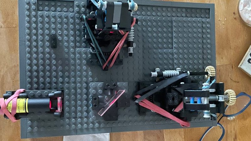
The build in question is a Michelson interferometer; [Kyra] was inspired to build it based on earlier work by the myphotonics project. She was able to assemble holders for mirrors and a laser, as well as a mount for a beamsplitter, and then put it all together on a LEGO baseboard. While some non-LEGO rubber bands were used in some areas, ultimately, adjustment was performed with LEGO Technic gears.
Not only was the LEGO interferometer able to generate a proper interference pattern, [Kyra] then went one step further. A Raspberry Pi was rigged up with a camera and some code to analyze the interference patterns automatically. [Kyra] notes that using genuine bricks was key to her success. Their high level of dimensional accuracy made it much easier to achieve her end goal. Sloppily-built knock-off bricks may have made the build much more frustrating to complete.
We don’t feature a ton of interferometer hacks around these parts. However, if you’re a big physics head, you might enjoy our 2021 article on the LIGO observatory. If you’re cooking up your own physics experiments at home, don’t hesitate to drop us a line!
Thanks to [Peter Quinn] for the tip!


I think that’s a neat build and should work fine where changes over time aren’t important. However the plastic used, as most plastics do, has a high coefficient of thermal expansion, which would negate any benefits of precision they had if the temperature changed. I used to make holograms and had a decent homebrew setup. I learned to avoid making plastic parts early on, and making holograms of plastic objects would be difficult as well, with the characteristic banding and areas that would disappear completely that is indicative of movement during exposure.
Perhaps LEGO will consider a line of Invar or zerodur LEGOs?
u wot m8?
Plastic is not metal, it doesn’t expand lol.
… Where on earth did you get the idea that thermoplastics don’t expand when heated?
ABS has a moderate coefficient of thermal expansion, which means it expands and contracts with changes in temperature. This property is important in applications where dimensional stability is crucial. Designers and engineers need to consider the CTE of ABS when accounting for thermal expansion or contraction in their designs to prevent warping or distortion.
Legos are made of ABS plastic, which has a moderate coefficient of thermal expansion, which means it expands and contracts with changes in temperature. This property is important in applications where dimensional stability is crucial. Designers and engineers need to consider the CTE of ABS when accounting for thermal expansion or contraction in their designs to prevent warping or distortion.
Please get yourself a 3D printer and reconsider this belief. You´ll learn much and it´ll keep you busy.
(Watches one of the overhang tests on the Torture Toaster curl up and crash the machine)
How close to “doesn’t at all” do you mean? Because there are plenty of materials that are “essentially” zero CTE: Zerodur, ULE Glass, Invar, even Pyrex.
Would really like to see details how the mirror mounts are built. For length dependent measurements a linear stage for one mirror is required. For example this 3D printed flexure: https://www.thingiverse.com/thing:6618214
cool project
I saw a build like this just last week at the new University of Nottingham exhibition at the Djaogly space.
https://www.nottingham.ac.uk/news/cosmic-titans-exhibition
LEGO brick is 8mm wide and 9.6mm tall. One plate is 3.2mm or one-third of a brick. With some creative tricks, you can get 1.6mm or half-plate steps without ruining LEGO part.
I’d start with LEGO CAD-type program, Stud.io is fairly easy to start on and does allow you to move part or rotate part with precision. LDraw and LEGO Digital Designer (obsolete from LEGO, but somewhat supported by community) are other common options.
All are free to use. Some basic understanding of 3D CAD would help a lot.
Thermal expansion over time is a real issue, and working with LEGO in a more serious laser system would be a nightmare. I’ve worked in an fs-pulsed laser laboratory, and we experienced beam path shifts of about 0.05 mm per meter throughout the day, despite having a 30KW AC system in place.
This setup, however, is designed primarily as an instructional tool—its purpose is to teach the principles of interferometers rather than serve as a practical system for production use. The reproducibility of angular shifts is a major challenge, making it difficult to achieve stable interference. Even with high-end Newport or Thorlabs mounts and breadboards, the system remains highly sensitive to vibrations.
Because of these challenges, many educators opt for simulation tools to demonstrate the concepts in class. While practical, I find this a bit unfortunate. Experiencing firsthand how difficult it is to align an interferometer—and then finally succeeding—reinforces the learning process. Seeing interference pattern shifts due to an inserted object with a different refractive index is a valuable educational moment.
Since using a ruler on the screen isn’t effective for measuring fringe shifts, the idea behind adding a camera was to enable more precise measurement of these changes.