
LEGO! It’s a fun toy that is popular around the world. What you may not realize is that it’s also made to incredibly high standards. As it turns out, the humble building blocks are good enough to build a interferometer if you’re so inclined to want one. [Kyra Cole] shows us how it’s done.
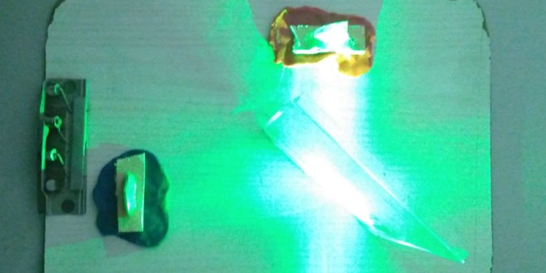
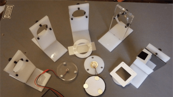
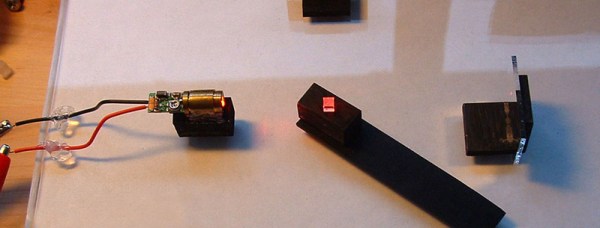
The build in question is a Michelson interferometer; [Kyra] was inspired to build it based on earlier work by the myphotonics project. She was able to assemble holders for mirrors and a laser, as well as a mount for a beamsplitter, and then put it all together on a LEGO baseboard. While some non-LEGO rubber bands were used in some areas, ultimately, adjustment was performed with LEGO Technic gears.
Not only was the LEGO interferometer able to generate a proper interference pattern, [Kyra] then went one step further. A Raspberry Pi was rigged up with a camera and some code to analyze the interference patterns automatically. [Kyra] notes that using genuine bricks was key to her success. Their high level of dimensional accuracy made it much easier to achieve her end goal. Sloppily-built knock-off bricks may have made the build much more frustrating to complete.
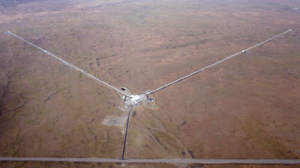
We don’t feature a ton of interferometer hacks around these parts. However, if you’re a big physics head, you might enjoy our 2021 article on the LIGO observatory. If you’re cooking up your own physics experiments at home, don’t hesitate to drop us a line!
Thanks to [Peter Quinn] for the tip!
 In the late 1800s, no one knew what light was. Everyone knew it behaved like a wave some of the time, but all waves need to travel through some propagation medium. This propagation medium was called the luminiferous aether and an attempt to detect and quantify this aether led to one of the coolest experimental setups of all time: the Michelson-Morely experiment. It was a huge interferometer mounted on a gigantic slab of marble floating in a pool of mercury. By rotating the interferometer, Michelson and Morely expected to see a small phase shift in the interferometer, both confirming the existence of a luminiferous aether and giving them how fast the Earth moved through this medium.


