
Everyone loves wireless power these days, almost vindicating [Nikola Tesla’s] push for wireless power. One reason why transmitting electricity this way is a terrible idea is the massive losses involved once you increase the distance between transmitter and receiver. That said, there are ways to optimize wireless power transfer using inductive coupling, as [Hyperspace Pirate] demonstrates in a recent video.
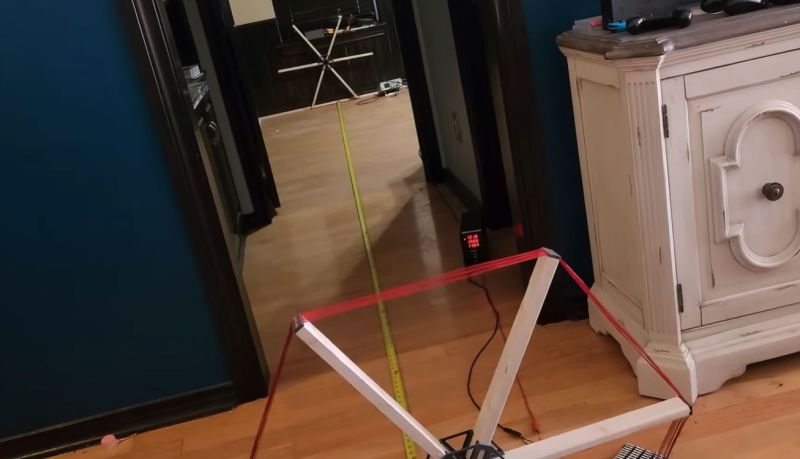
Starting with small-scale proof of concept coils, the final version of the transmitter is powered off 120 VAC. The system has 10 kV on the coil and uses a half-bridge driver to oscillate at 145 kHz. The receiver matches this frequency precisely for optimal efficiency. The transmitting antenna is a 4.6-meter hexagon with eight turns of 14 AWG wire. During tests, a receiver of similar size could light an LED at a distance of 40 meters with an open circuit voltage of 2.6 V.
Although it’s also an excellent example of why air core transformers like this are lousy for efficient remote power transfer, a fascinating finding is that intermediate (unpowered) coils between the transmitter and receiver can help to boost the range due to coupling effects. Even if it’s not a practical technology (sorry, [Tesla]), it’s undeniable that it makes for a great science demonstration.
Of course, people do charge phones wirelessly. It works, but it trades efficiency for convenience. Modern attempts at beaming power around seem to focus more on microwaves or lasers.


Yeah, that dipole-dipole inverse-cube law really bites here.
Large phased array transmitters (antennas multiple wavelengths in size) and target tracking (like Energous and Ossia do) can help push that closer to inverse-square. But until you make the transmit and receive apertures (antennas or lenses) many wavelengths in size, you’re doomed to suffer the consequences of the Friis Transmission Equation.
It’s only one of the two. It seems like it should be both, but that’s because Friis is far field, and once you have even one of the antennas huge, it’s not far field anymore.
Just imagine a small patch antenna (with a ground plane behind it so it’s directional. Now surround the antenna with a bowl: you’ll capture literally everything (modulo losses in medium/antenna).
Friis just comes from diffraction: once one of the antennas is so big the other can resolve it spatially, it doesn’t work anymore.
Exactly. Said more clearly than I did.
Consider in far field that the path attenuation formula has no input for size of radiating or receiving antenna.
Inverse square law is inverse square law whether between antennas 2 miles away or between the earth and Voyager 1, billions of miles away.
Yes .. Sorry, Tesla Zenneck waves guys. It’s really important that antenna “gain” isn’t gain at all, but is refocusing energy radiated in directions that aren’t considered useful into desired directions. You can never get more power out of an antenna than you put in (with “gain”). And there’s never been demonstrated in far field the ability to operate in any mode that wasn’t 20log(10) distance for path attenuation.
It makes a great fantasy or conspiracy theory, but not the reality.
Hmmppf… it’s got nuthin’ next to M5 !
https://www.youtube.com/watch?v=z3z1Xi_5m80
Thought this went the way of the Space Elevator.
What does “[Tesla’s]” signify as used in the article? I don’t know what brackets around a name means. I see it often here but don’t really know, and I don’t see a FAQ here that might tell me.
Thanks for any clarification.
-Ed
Our house style is to use brackets around names which, for us, are often hacker handles. So it might be confusing here to say “We noticed that a dumb d00d built a robot…” Instead, we say “We noticed that [a dumb d00d] built a robot…” We sometimes omit them for famous people with real names (and sometimes not) but, in this case, we felt like [Tesla] was more obviously the guy and not the company.
I think it would be more consistent and intuitive if you just made sure to put Nikola Tesla to differentiate the two. Brackets for hacker handles is nice but since Tesla has a first name why not use that?
If he’s referenced multiple times in an article, some would find it tedious to keep reading “Nikola Tesla” over and over. Complaints would ensue. There’s always somebody who doesn’t like something. Myself, I wish certain authors would spend more time reviewing their spelling and grammar (or probably more effectively, have someone else read their work).
We tend to be people.
Yeah the delegation methodology.
I hope nobody in the neighborhood is trying to listen to an AM radio
I hope he has a Ham license. Should use 136 khz instead of 145 khz.
It does not belong in a ham band. It should be running in an ISM band, but it would have to be completely redesigned to operate on 6.78MHz or 13.56MHz.
Even better would be 300 THz. It’s not subject even to ISM restrictions, not even regulated by the FCC. There is an OSHA safety regulation (defined by ANSI Z136.6), but that’s about it.
145 khz is not.
136 khz is a Ham frequency, at least in Europe
73′
Though limited to one watt.
Also, with the multiple tens of volts that even the smaller circuits can generate within a resonant receiever… is there not a danger than any electronic device brought near to the bigger power transmitter could find “dangerously” (anything over 3.3V will easily be dangerous for some microcontrolelr circuits, anything over 5V tends to endanger most 74 series logic…) large voltages being induced in parts of the circuit never designed to take them? Unless someone can provide an argument against my guesses here… (because even an LC parallel pair which isn’t perfectly tuned for resonance still tends to pick up a more limited strength of induced sine wave when near to a resonating emitter) … well I’d be scared to run a wireless power transmitter of this kind anywhere near to computers, phones… there must be plenty of LC pairs within them, including unintentional ones simply because a particular resistor near to a capacitor might have inductive properties…
Fascinating demonstration, but not much to do with how Tesla planned to install wireless power. His idea was to use the Earth and the ionosphere as a “ball-in-ball” capacitor, between which any elevated conductor and ground would provide voltage with near-zero loss.
With these efficiencies, what ISN’T wireless power transfer?
If I “transmit” power by playing a 60Hz sine wave, and “receive” it with a microphone, does that count?
What if I use a phased array of ultrasonics and catch it with a directional mic?
I feel like even acknowledging a project like this does harm by validating the “free energy” and “Tesla” wackos…
When I first saw the picture I thought the whole apparatus would spin really fast and fling the electrons. I was pretty excited about that.
That’s whats wrong with kids these days:
Too many flinging electrons.
It is possible to set up two masers to be resonant in such a way that they form a high-power and high-efficiency energy transfer channel. Here’s the deal with using a maser to beam energy with an antenna no bigger than 2 meters across. In space, where there’s no air to mess things up, you could send energy hundreds of kilometers, but on Earth, the atmosphere sucks up and scatters the microwaves, so you’re lucky to get a few kilowatts over 10 kilometers—and that’s only if the weather’s on your side. The small antenna keeps things limited; bigger ones would mean more power and range, but with this setup, you’re working with some pretty tight constraints. Still better than any other wireless option.
All done and tested by billion dollar companies… Tfipwr.com formerly transferfi.com
What an amazing buzz this would make in the radio spectrum… are any bandpass filters used? The harmonics will be spectacular.