It is easier than ever to produce projects with nice enclosures thanks to 3D printing and laser cutting. However, for a polished look, you also need a labeled front panel. We’ve looked at several methods for doing that in the past, but we enjoyed [Accidental Science’s] video showing his method for making laminated panels.
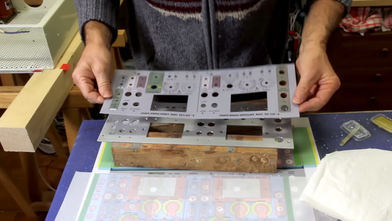
His first step is to draw the panel in Inkscape, and he has some interesting tips for getting the most out of the program. He makes a few prints and laminates one of them. The other is a drill guide. You use the drill guide to make openings in the panel, which could be aluminum, steel, plastic, or whatever material you want to work in.
The laminated print goes on last with just enough glue to hold it. Is it a lot of work? You bet it is. But the results look great. There are a number of things to look out for, so if you plan to do this, the video will probably save you from making some mistakes.
There are many ways to get this job done. We’ve asked you for ideas before and, as usual, you came through. If you want a different take on laminated panels, there are a few different tips you can glean from this project.


When printing something make sure to check if your printer keeps correct dimmensions. In my case, to achieve accurate results from my laser printer I have to scale page with using 101,4% factor. Otherwise printed panel (or toner-transfer PCB, or cutout in aluminium or whatever) would be too small in one dimmension. Length seems to be perfectly accurate.
Thanks for the memories!. gEDA pcb printed a calibration page with values to feed back in to the program.
I did this for a switch panel on my old Jeep… all manually, of course – being prior to laser cutters and 3d printers. Lots of careful drilling, shearing, Dremel-ing, and filing. The hardest part was getting the backlit labels right. I chose printing on transparency sheets with a common printer – as I did for circuit masks. To get the label opaque enough, I had to print them twice over the same sheet. Alignment of the multiple passes was a painfully repetitive “broad side of a barn” process. Finally got them all satisfactory for the purpose.
The most annoying task is making round scales. There are plugins and tools for that but adding values/text most of the time is a manual job…
Inkscape can fit text to an arbitrary path, including arcs. Would that help ?
Inkscape’s transforms will let you do something like “replicate this line, translate, and rotate it 5 degrees” (from the simple transform to arbitrary transformation matrix), which is probably more usable for something like tick marks.
Not that applying text to an arc won’t work, that’s just probably not what jansprojekteJanW was asking.
This is a nice method. I’m lazy. I have PCBs made, with solder resist and silkscreen colours as I need. Much easier. But multicolour panels like in the video aren’t possible.
With the pcb method it’s possible to have electronics on the back, and/or screening. Can have various FR4 thicknesses, and even aluminium if required.
It’s very cost effective for low volumes. The results look great, and are super precise. I’ve even been known to have edge plating for some extra bling!
https://jlcpcb.com/resources/multicolor-silkscreen-pcb
+1 ….. PCB panels every time ….. super easy and look great.
Yes agree, Al-“pcbs” with solder-mask, silkscreen print & graphics, CNC slots & cut-outs; made and shipped quickly for very low cost – it’s a real game-changer.
Or also ordinary FR4, for sure. Even cheaper.
QCAD is a better choice for drafting, IMNSHO. Inkscape is for “artistic” drawings and SVG, QCAD is for technical drawings and DXF.
‘Professional-looking’?
I once had a boss who was always going on about us being ‘professional looking’.
He was the worst manager I ever had the displeasure of working for.
Pure marketer, trying to run a coding and IT team.
Beware any industry that sells pure commodities, marketing always rules there…
Anyhow:
I got another job, then made the worst mistake of my working life.
I accepted their counter-offer, almost doubled my pay.
He told the entire department they weren’t getting a raise because I had taken the entire ‘raise budget’.
Of course I heard about it.
Told them all I had taken 180% of the ‘raise budget’.
They should all jump up and down until their balls dropped, then find a better job.
Only the lesbian took my advice…
I was gone anyhow, 6 months later.
They intended to ‘use me up’ for a year then fire me, so I did nothing (but ferment trouble) and found yet another offer.
The big raise meant my next new job was much better paid.
Wasn’t that bad a mistake, I guess.
Anyhow, beware anybody who says ‘professional-looking’, actually ‘professional’ is much much better.
Actually professional is writing on the front panel in sharpie/barefoot in the office.
Cool story, bro.
Dry moly spray and a laser looks pretty good and has quite fine resolution. Only black, though.
But MUCH faster and easier.
Anyone have a good source for getting the front panels machined/cut? Ideally mail-order. Send ’em the metal and some form of cutting data and get back a cut panel?
I only know of it anecdotally, but this sounds like what I’ve heard that Send Cut Send does.
I ‘ve used a company called Front Panel Express in the past. Very nice panels! But these days I use a laser to do either front-engraved or back-engraved front panels out of 1/16” sign engraving plastic.
What I found is that outside advertising boards are also a cheap option (even including brushed aluminium). That is if you can live with dibond sandwich panels. Lots of companies include cnc contouring. If you ask nicely, they also do the inside holes. O.o.m. 10 Euros for 19″ front panels.
With the design you have to take into account that the print and contouring are not always perfectly aligned (in experience ca .5mm shifts possible). And typically I see they use 2mm mil, so expect rounded inside corners.
I have had made front and back a panels in Dibond for the power supply I was making. They look really great, and it was cheap. I am not sure why it is not a more popular panel making method.
Anyway, this was seven years ago and I still haven’t finished building that power supply, but on the plus side, it will look great once I will have completed the design.
It will have a nice “retro” touch by that time :)
Some military equipment I’ve worked with has beautiful front panels, which could definitely be replicated with hobbyist equipment (to varying levels of quality depending on time and effort expended).
For the milspec ones, first an armature is CNC-milled from something hard like aluminium or an engineering plastic. This serves as the main structural element. Anything that needs to be illuminated, like text, is milled all the way through. Some elements are only milled partway, like dividing lines between functional groups – these will not light up later.
Anything that’s been engraved is then filled with a thick white paint, or coloured epoxy resin, which brings it up slightly above the surface level of the panel. The panel is then flipped over, any mounting inserts are fitted, and then it’s filled with a epoxy resin which cures translucent. This serves as the diffuser for backlighting, which massively improves the quality of the final appearance.
Once this layer has cured, the back of the panel is CNC-milled with a recess which accepts the electronics. The front is then tidied up – presumably by a sanding or milling process to remove any overfill of the legends’ infill paint – and then painted. I assume this could be done with something that only sticks to the base layer and not the epoxy, or you could just paint everything and then repeat the CNC milling operation to remove it from the legends once it’s cured.
The controls and indicators (switches and LEDs) are all mounted onto a large PCB which sits behind the panel. This is held on both by threaded standoffs which are moulded into the epoxy infill, and by the retaining nuts on the switches and indicators. Surface mount LEDs provide the panel illumination.
You could easily replicate this process using a 3D-printed panel and resin infill – just remaining aware that thin layers will be required to keep it from distorting due to any exothermic reaction as the resin cures!
The resulting panels will outlast most equipment and continue to look nice forever.
I used to draw up panels in Illustrator from the supplied drawings, add registration marks for laser cutting, and then have our Repro department color zerox them onto Polypaper. Then I would apply 3M film adhesiveon the back, clear polyester laminate on the front, then orient the panel sheet in a CO2 laser engraver and cut them to shape. This worked great for durable panels that had a lot of type and colors, like complex ethernet port racks.
HELP: What I still haven’t been able to figure out is a good way to cleanly integrate a glass window for a touchscreen (or non-touchscreen) LCD.
I have been using M5 Stack Core modules for projects that need a clean LCD integration. However, this is not a very economical route (particularly if I am not using a majority of the peripherals packed inside). Other times my project needs more I/O pins than what are available on the M5 Stack, or I want a display larger than ~2″ (50mm).
I haven’t really been able to come up with a DIY way to cleanly integrate a window into an aluminum or ABS enclosure / panel. I was thinking of getting a small / cheap desktop CNC mill to 1) cut out the window hole in the enclosure/panel, then 2) mill the window, such that it has the matching window size/shape, plus flanges to hold it in place and at the right depth when inserted from the rear of the panel and glued. Does glass even mill well? Any other ideas? I would like the window to be flush with the surrounding surface…
I have made front panels with display openings by making it out of an entire piece of acrylic.
Everything is seen from the back side
1. Mill out the contour of the display window with a CNC.
2. Remove the protective film from the panel except the display opening.
3. Spray paint the exposed surface (might need to coats)
4. Mill out holes and text in the painted surface
5. Spray paint the openings with the colour of text you want.
6. Remove protective film from display opening.
This method needs some tuning to figure out the ideal depth and tool to use, but once you have that sorted for the material you use, it looks great.