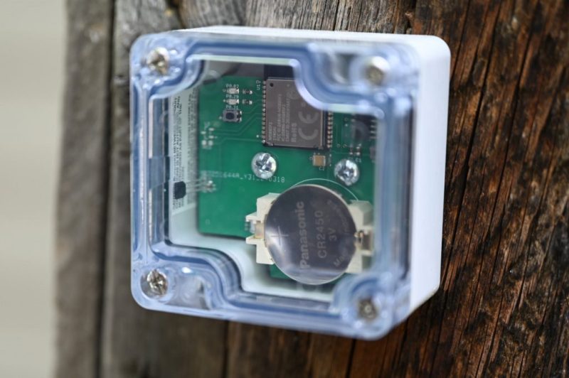
Recently [Glen Akins] reported on Bluesky that the Zigbee-based sensor he had made for his garden’s rear gate was still going strong after a Summer and Winter on the original 2450 lithium coin cell. The construction plans and design for the unit are detailed in a blog post. At the core is the MS88SF2 SoM by Minew, which features a Nordic Semiconductor nRF52840 SoC that provides the Zigbee RF feature as well as the usual MCU shenanigans.
Previously [Glen] had created a similar system that featured buttons to turn the garden lights on or off, as nobody likes stumbling blindly through a dark garden after returning home. Rather than having to fumble around for a button, the system should detect when said rear gate is opened. This would send a notification to [Glen]’s phone as well as activate the garden lights if it’s dark outside.
Although using a reed relay switch seemed like an obvious solution to replace the buttons, holding it closed turned out to require too much power. After looking at a few commercial examples, he settled for a Hall effect sensor solution with the Ti DRV5032FB in a TO-92 package.
Whereas the average person would just have put in a PIR sensor-based solution, this Zigbee solution does come with a lot more smart home creds, and does not require fumbling around with a smartphone or yelling at a voice assistant to turn the garden lights on.


Makes me almost wonder if he could have put a solar cell and energy harvesting chip in there and use a rechargeable battery. Of course his design and power profiling in the in-depth article is pure genius. I just think if you are that skilled, you could go beyond 1-2 year coin cell lifetime with some good ole sun energy.
(Wish I could design anything that energy conserving myself.)
It’s not very difficult to get a MCU to run at very low power. It’s getting it to do something useful at the same time that is difficult.
I design wearables as my job, and battery energy conservation is really not that hard.
On the hardware level you just power the MCU directly, any circuitry that has a standby/quiescent current consumption that is over 1-2uA goes behind a power switch or multiple. This circuit is only powered when needed, and even then the component selection should prioritize low power devices.
On the firmware side you keep the MCU in sleep for as most of the time, and wake it up at set intervals for the shortest time possible, for example for 300ms every five minutes.
Understanding how Coin cells work is also important. For example they don’t like current spikes. Repetitive current spikes will increase the internal resistance if the cell permanently. To avoid this, bulk capacitance (ceramic) and careful sequencing of the events will greatly improve battery life.
The capacity of a 2450 is 620mAh to 2.0V, so say (average 2.5V) 1.55Wh which is about 4.2mWh/day.
A small garden light 60x60mm solar panel is typically 0,25W, and I find figures of solar panel efficiency going to 10% on a cloudy day. So say a winter day of 8 hours, this cell would still produce 0,2wH/day, which is still about 45 times the daily energy consumption, so I guess that would be very doable.
Thanks for sharing your knowledge on the subject! I saved your post to a text-file so I can evaluate how much margin I have if I attempt something similar. I like to stay humble about my limited skills, but this makes me want to purchase some cells off Ali and try myself. I have a very illuminated balcony and I want to put some sensors out there for UV-index, temp, humidity and more. All low powered IC/ASIC ones. Realistically speaking I will still have to go the NRF route I assume. They are more or less market leader in low energy wireless. Regular 433 MHz transmitters off Ali are too power hungry.
I am always very happy when people inspire me or reply with calculations or conservative estimates.
“Thanks for sharing your knowledge on the subject! ” That’s too much honour, I was just wondering, googled around for some logical values, and did the math with some very liberally educated guesses.
Carl, wouldn’t a solar garden light from a Dollar/Pound/Euro store be even cheaper than Aliexpress? It could be rain resistant as well.
You need about 175 µW on average, so the panel should be sized at 2 mW or greater (10x) and something that size from the usual reliable sources (not Aliexpress) costs between $1-3 in single quantities.
If you can find a garden light in that price range, you might get something but you don’t know the voltage or power of the panel, so it might not work for you, or you need to go through extra steps (more components, more $$) to make it work.
For anyone going down this path, please be aware that these cheap garden lights often use nickel-cadmium rechargeable cells. Cadmium is a toxic heavy metal, so please remember to take unused, old, or dead cells to proper e-waste or battery recycling. Don’t just throw them in regular landfill.
It’s easier to estimate using the average year-round capacity factor for your location. About 5% in Sweden and 15% in Spain. This accounts for seasonal variation and overcast days.
The only other thing you have to mind is having enough batteries to account for the seasonal variation. In Sweden you need 4-6 months worth – much more than theoretically necessary because of the cold temperatures – while in Spain you pretty much need nothing because the length of the day hardly changes. A big capacitor would probably work.
That’s of course assuming you can place it in a properly lit location.
The difference between a normal sunny day and a complete overcast is about 1000:1 so if you’re looking to oversize the panel to make it operate in the shade just by the ambient light, you’d need a panel in the range of 1-2 W which is about the size of your palm.
Seems like you could charge a capacitor and run off that, keeping the battery as main power and extending it’s life.
Although in this application you could modify the gate to bring multiple magnets across the case and swap the sensor for a coil to harvest power.
I use an ikea parasoll which was about a tenner. Fruns on a rechargeable 1.2. It uses the efm32 afaik …
You can get reed switches that are magnet off/ closed door-open circuit. Sounds like the hall effect sensor sips power so that’s a great solution.
The issue was that reading the sensor requires a pull-up resistor, so one of the logic states will always draw extra current whether it’s a normally open or a normally closed switch. The door can remain open or closed for long periods of time, so it’s possible to drain the battery by forgetting to close the door.
Since the change in logic level is probably what drives the wake-up interrupt for the MCU, you can’t leave the logic state undefined or else it would trigger the wake-up event from random noise. I.e. you can’t use clever tricks to poll the input to detect whether the switch is open or closed without a pull-up resistor.
The Hall sensor has a push-pull output, meaning that the logic state is always defined as either high or low, which means the MCU doesn’t need to enable its pull-up resistor on the input and there’s no variable current draw depending on the state of the switch.
You can poll using a switched pull up very easily, so the pull up only dissipates power for a brief pulse of a few ms rise time. This would give a negligible draw compared to the ZigBee operations. If you are responding to a switch close event a capacitor can limit this to a brief pulse also
Yes, but then you assume the MCU will wake up periodically and rather frequently (once a second maybe?) to poll it, which requires far more energy than waiting for the input to change and wake up on that.
I thought about that – you can detect the pulse edge but then you need to reset the capacitor somehow with the switch pulling it one way only. The system would respond quickly to one event like opening the door, but slowly to the opposite case (discharging the capacitor on closing the door) and the digital inputs of an MCU tend to consume a lot of power when the input is drifting slowly through the hysteresis range.
How would you implement it?
2450s are absolute units, I use those industrially all the time and they get changed like every 5-10 years it’s wild
Should use them for computer backup, seems more than twice the usual 2032, maybe 3-4x.
Solution: two reed switches, one normally open and another normally closed. No pull-up required and zero quiescent current. Just needs a resistor to prevent shoot-through if both happen to remain on at the same time.
There are also SPDT reed switches.
https://comus-intl.com/wp-content/uploads/2018/10/RI-90GP.pdf
Yeah my solar WiFi camera is pointed at the front gate and lights up the entire front garden when motion is detected.
I don’t know why people are doing 9000iq things for something as trivial as a few solar garden lights they could use instead.
Unless of course they’re in some big stately home, but then I would presume they could afford something proper.
I am wondering though, if there is light in that garden, there is electricity. Could run anything from that. In what way would a reed switch cost too much energy?