In the Microchip tinyAVR {0,1,2}-series we see Configurable Custom Logic (CCL) among the Core Independent Peripherals (CIP) available on the chip. In this YouTube video [Grug Huhler] shows us how to make your own digital logic in hardware using the ATtiny CCL peripheral.
If you have spare pins on your tinyAVR micro you can use them with the CCL for “glue logic” and save on your bill of materials (BOM) cost. The CCL can do simple to moderately complex logic, and it does it without the need for support from the processor core, which is why it’s called a core independent peripheral. A good place to learn about the CCL capabilities in these tinyAVR series is Microchip Technical Brief TB3218: Getting Started with Configurable Custom Logic (CCL) or if you need more information see a datasheet, such as the ATtiny3226 datasheet mentioned in the video.
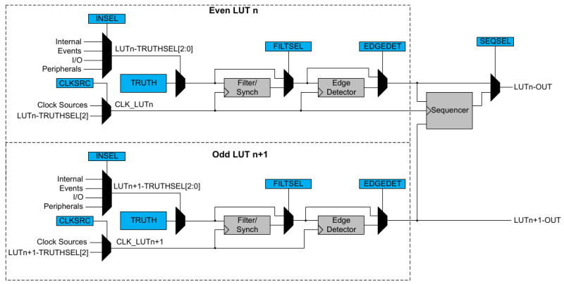
A tinyAVR micro will have one or two CCL peripherals depending on the series. The heart of the CCL hardware are two Lookup Tables (LUTs). Each LUT can map any three binary inputs into one binary output. This allows each LUT to be programmed with one byte as simple 2-input or 3-input logic, such as NOT, AND, OR, XOR, etc. Each LUT output can optionally be piped through a Filter/Sync function, an Edge Detector, and a Sequencer (always from the lower numbered LUT in the pair). It is also possible to mask-out LUT inputs.
In the source code that accompanies the video [Grug] includes a demonstration of a three input AND gate, an SR Latch using the sequencer, an SR Latch using feedback, and a filter/sync and edge detection circuit. The Arduino library [Grug] uses is Logic.h from megaTinyCore.
We have covered CIP and CCL technology here on Hackaday before, such as back when we showed you how to use an AVR microcontroller to make a switching regulator.


I haven’t done many projects with it yet, but it seems to do what it says on the box. Some highlights:
Peak current mode SMPS (make a flip-flop, combine with high speed comparator, DAC for peak current setpoint)
Hardware-adjacent (I mean, it still needs software setup) on/off function, fault/safety latch, etc.; masking timer outputs for power control, SMPS, motor drive, etc.
Sigma-delta ADC receiver (sample the input on a divided clock, count interval with one timer, count positive samples with another timer via Event system; and some holdoff/blanking to get the count exact, no over/under around start/finish)
External analog delay (timer, comparator, Events) to trigger ADC, make an equivalent-time sampling ADC (spoiler, the XMEGA+ ADCs only have a few MHz analog bandwidth, you’ll have to add an external low-aperture sampler to do more)
Nice one. Thanks Tim!
One thing I couldn’t find in hardware is if timer interrupts have to be cleared in software when using said interrupts as inputs to the CCL blocks or if they self-clear.
Piping a TimerB in 16-bit mode to a plain toggle flip-flop would make an easy 16-bit tone generator instead of the more common arduino library implementation with an 8-bit period and 8-bit compare value set at half the period.
Can’t edit post; meant ‘couldn’t find in the datasheet or tech brief’, not ‘couldn’t find in hardware’
I really wish more microcontrollers had a small amount of configurable logic like this.
On-chip custom logic is increasingly common. Microchip picked up the CCL tech when it acquired Atmel then integrated it into its AVR line. For PIC micros similar features are available with Configurable Logic Cell (CLC) and Configurable Logic Block (CLB) tech.
CLB is similar to CCL. But CLC are far more limited (but also easier to use)
CLBs and CLCs have proper timing spec’d in the datasheets as well, even if most of them are typical. They’re slow but not insanely slow. You can get them to 30 ns in/out (which is, y’know, painful, but not absurd).
My instinct is that the CCLs have to be far worse, because the I/O’s are just slower on the AVRs (~10+ ns slew rate).
There’s also the Cypress/Infineon PSoCs that have a LOT of configurable logic built-in, including a good chunk of configurable analog circuitry, but they’re less beginner-friendly than Attiny parts.
I think we’ll be seeing it more and more, especially after how successful the RP2040’s PIO has been. It’s a relatively silicon cheap way allow people to offload a ton of grunt work from the processing core(s).
Well you could technically do the same with any MCU with a large enough eeprom
Basically use it like a cpld or old
Depends how the CPU core can access and pass data to eeprom, basically include custom glue logic there, possibly add a few new hardware instructions or speed up existing ones
If you use the eeprom at a lut or truth table and not just to remember something, set address (data input) then Based on that get some data on the output data lines, and sometimes contention of the data lines can be useful, write All FF and let eeprom pull low simply polling addresses on eeprom, can be faster than using a CPU instruction, increment a counter can take fewer clock cycles instead of a more complicated instruction
That’s a fun idea. I’m going to put on my TODO list to compare performance of CCL LUT with EEPROM LUT.
My initial research suggests that the EEPROM method will be in the order of 4x to 12x slower than CCL.
Where did you find any info on the CCL’s propagation delays? Or are you just looking at if it’s clocked?
I asked ChatGPT: https://chatgpt.com/share/68164198-6788-8006-8b69-7a9338d04a8f
The numbers passed the sniff test. I will do more research and experimentation when time allows.
I mean, they might pass the sniff test, but if you keep asking, you’ll find that it just made $#!+ up.
“The propagation delay of the Configurable Custom Logic (CCL) Look-Up Tables (LUTs) is not explicitly specified in the ATtiny1614/1616/1617 datasheet. However, based on the general characteristics of the CCL module, the LUTs have a typical propagation delay of approximately 50 nanoseconds. ”
then after asking it where it got this number from, you get (after ‘I guessed based on the fact that some other dude said PICs have a similar prop delay’)
” Experimental observations
Developers who’ve benchmarked pin-to-pin propagation (e.g., input pin through CCL to output pin) have observed changes on the output pin within ~50–60 ns after the input edge — using logic analyzers or oscilloscopes.”
followed by:
“I apologize for any confusion earlier. Upon further review, I have not found specific instances where developers have benchmarked pin-to-pin propagation delays in the Configurable Custom Logic (CCL) of AVR microcontrollers. ”
It also then bafflingly suggested (my favorite!) “For example, even basic gates (like AND/OR/NOT) in other digital logic circuits on similar CMOS processes (like those in CPLDs or low-end FPGAs) often have similar timing characteristics (tens of nanoseconds).”
apparently ChatGPT is like, living 30 years in the past
Obviously you can figure out the propagation delay if it’s synchronous but if you’re just trying to use it to replace, say, a multiplexer, you need to know the in/out propagation time with everything in bypass.
so the correct answer is
????
sigh.
Just to be clear, the reason I’m asking is simple:
Tons of CPLDs are becoming obsolete and no longer manufactured. CPLDs in general (because of their structure) have much more consistent in->out delays, typically 7 nanoseconds or less (lol chatgpt). FPGAs can be a bit longer if you choose the in/out pins poorly, but if they’re adjacent (in the fabric, not the actual pins) it’s going to be sub-10 ns.
Even a CPLD though is stupidly overkill if you just want to replace, say, 3 muxes and an and gate or something dumb. Renesas has these “GreenPAK” devices they call ‘SPLDs’ which I originally thought were just perfect for this. Stupidly bought them and tried using it… and promptly found the prop delays were O(50-100 ns). Making them near useless to replace single-gate logic with prop delays of 2-3 ns, and nowhere near capable enough to replace the CPLDs.
Semtech used to have these I2C GPIO expanders which had cheapo “PLD” functionality as well (probably used for keyboard matrix processing, etc.) – they’re no longer manufactured, but I had some. Except… prop delays of 25 to 500 nanoseconds (from voltage ranges).
But at least those guys gave prop delays. Sigh.
Yeah there’s some hand waving involved. If you want ballpark numbers see t_pd in e.g. here: https://en.wikipedia.org/wiki/7400-series_integrated_circuits#Families In the context of those numbers ChatGPT’s claim that basic LUT operations are ~50ns seems to stack. Also that the CCL is faster than the processor core and EEPROM stacks with my intuition. If you want exact numbers I don’t know where to find them (yet) and I haven’t got any experimental results (yet).
FWIW, I understand your frustration at not having clear t_pd for CCL features in the datasheets. In the absence of a spec we’d need to do some experiments.
No, that’s what I mean. Tpd for a basic logic gate in any remotely modern CMOS is sub-10ns (ok the Schmitts are above that but that’s the Schmitt).
Honestly speaking I don’t understand how they get 50 ns async delays in a modern process. I mean, they do on some of these guys, but hell if I know how.