You’re designing an oscilloscope with modest storage — only 15,000 samples per channel. However, the sample rate is at 5 Gs/s, and you have to store all four channels at that speed and depth. While there is a bit of a challenge implied, this is quite doable using today’s technology. But what about in the 1990s when the Tektronix TDS 684B appeared on the market? [Tom Verbure] wondered how it was able to do such a thing. He found out, and since he wrote it up, now you can find out, too.
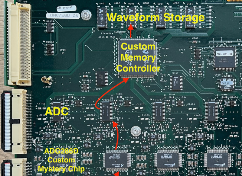
Inside the scope, there are two PCBs. There’s a CPU board, of course. But there’s not enough memory there to account for the scope’s capability. That much high-speed memory would have been tough in those days, anyway. The memory is actually on the analog board along with the inputs and digitizers. That should be a clue.

The secret is the ADG286D from National Semiconductor. While we can’t find any info on the chip, it appears to be an analog shift register, something all the rage at the time. These chips often appeared in audio special effect units because they could delay an analog signal easily.
In practice, the device worked by charging a capacitor to an input signal and then, using a clock, dumping each capacitor into the next one until the last capacitor produced the delayed output. Like any delay line, you could feed the output to the input and have a working memory device.
The scope would push samples into the memory at high speed. Then the CPU could shift them back out on a much slower clock. A clever design and [Tom] gives us a great glimpse inside a state-of-the-art 1990s-era scope.
While we haven’t seen the ADG286D before, we have looked at analog shift registers, if you want to learn more.


Great series of scopes- I think they are the last Tek series that were not Windows based- And many in the series could get a memory upgrade by the FAE running a disk- Had to buy this from Tek about (the year) 2000 on a TDS784C. No hardware changes- just enabling the built in hardware.
yes, the CCD captured the analog signal at high speed allowing the then-slow ADCs to convert at a more leisurely pace. my old 2430 worked that way to wit.
FISO (fast in, slow out) seems to be the magical search term. There are a few related patents from Tektronix, for example US4648072A. The switch matrix and phase shifted clocks could explain the interleaving of samples. The pattern repeating every ~195 samples could be varying RDSon of the different switching paths.
Nice! I wish I had known about the FISO magical search term before writing the blog post. It uncovers a lot of additional info including other patents, such as US6091619A.
I was in the advanced development group at Tek when the FISO was being developed and that was well after the 2430. The FISO part was used in Tek scopes for 30 years. And was only recently retired. It made Tek a lot of money.
oooh, didn’t know my bench scope had that feature!
[Tom Verbure] : you dropped an ‘e’ !
What makes you so certain?
;-)
Not to brag, but I’m kind of a world authority on the subject!
The first high speed digitizers I’m aware of used basically a CRT, but using a diode array instead of phosphor, and scanning the array with another electron beam. Those could reach at least 100GS/s (tek 7912AD), though for only a very limited number of samples.
I wonder what’s used nowadays for the very top-of-the-line scopes – are they able to directly convert to digital and store, or do they once again have something magical that allows captures to exceed the memory bandwidth?
I’ve used one of that (similar) series, the 7250 (rebranded French Intertechnique IN7000). Quite finicky, and the horizontal scale ended up really non-linear. If any of the CRTs used in acquisition failed, you were SoL. Ours was went out of calibration so there was a hand drawn horizontal scale to override the graticule marks on the CRT. This was the early 90’s and absolutely NO spare parts existed.
The 7250 was Huge and HEAVY (132 pounds).
Have heard that modern ones use, in addition to very high speed digitizers, a multi-band approach. I recall seeing waveguide in one of Shariar’s teardown vids. https://www.youtube.com/watch?v=U3w_EWgGQuk might be one?
Between this HaD article, and another recent one on a modernized GPIB adapter, it’s like someone is trying to inspire me to restore my TDS 540.
Although I have no idea whether my ‘scope is performing similar tricks to sample signals.