3D printing has simplified the creation of many things, but part of making something is knowing just how much you can rely on it. On the [BubsBuilds] YouTube channel, he built a cheap rotary table and then walked through the process of measuring the error inherent in any rotating system.
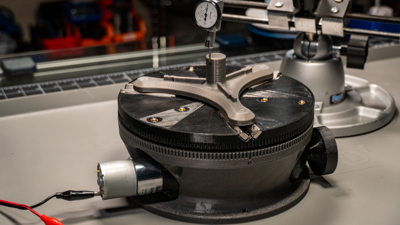
Starting with a commercial rotary table, [BubsBuilds] decided he wanted a rotary stage that was both lighter and had provisions for motorized movement. Most of the rotary build is 3D printed, with the large housing and table made from PETG, and the geared hub and worm gear printed on a resin printer. The bearings used to support the worm gear are common skateboard bearings. There is also a commercial thrust bearing and 49 larger 9.5 mm ball bearings supporting the rotating tabletop.
There are three different types of runout to be measured on a rotating stage: axial, radial, and angular. Axial runout is fairly straightforward to discern by measuring the vertical variation of the table as it rotates. Radial runout measures how true the rotation is around the center of the table. Angular runout measures how level the table stays throughout its range. Since these two runouts are tied to each other, [BubsBuilds] showed how you can take measurements at two different heights and use trigonometry to obtain both your radial and angular runout
This is a great walk-through of how to approach measuring and characterizing a system that has multiple variables at play. Be sure to check out some of the other cool rotary tables we’ve featured.


Did you have any time to breathe during this 9 minute video?
And what is happening at around 07:41?
You’ve found some kind of systematic error, and without analyzing it’s origin you just subtract it from your measurements to eliminate it?
At 7:41 he noticed the systematic error of excentricity between the 3 grooves center and the rotation axis. He then applies a software compensation for this (to get the roundness). If he applies the same software compensation when measuring a different part he could get the excentricity of that part between the 3 balls and cylinder. When only roundness is interesting one always subtracts whatever excentricity is found.
I saw those bit holders on ali and people commented that the thing was hard to get on a motor centered with the scrub screws. That made me think it’s funny that they have a self centering holder that is not self centering at the side that attaches to the motor.
People should buy two and glue the bit-holding ends together so both sides are self centering eh.
One never wants to congratulate someone’s clever word choice, because that only encourages them.
But I like the headline.
ﷻ