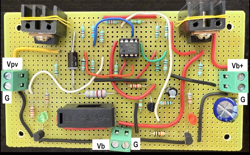
So you want a light that runs off solar power. But you don’t want it to go dark if your batteries discharge. The answer? A solar-mains hybrid lamp. You could use solar-charged batteries until they fall below a certain point and then switch to mains, but that’s not nearly cool enough. [Vijay Deshpande] shows how to make a lamp that draws only the power it needs from the mains.
The circuit uses DC operation and does not feed power back into the electric grid. It still works if the mains is down, assuming the solar power supply is still able to power the lamp. In addition, according to [Vijay], it will last up to 15 years with little maintenance.
The circuit was developed in response to an earlier project that utilized solar power to directly drive the light, when possible. If the light was off, the solar power went to waste. Also, if the mains power failed at night, no light.
The answer, of course, is to add a battery to the system and appropriate switching to drive the lights or charge the battery and only draw power from the mains when needed. Since the battery can take up the slack, it becomes easier to load balance. In periods of low sunlight, the battery provides the missing power until it can’t and then the mains supply takes over.
Comparators determine whether there is an under-voltage or over-voltage and use this information to decide whether the battery charges or if the main supply takes over. Some beefy MOSFETs take care of the switching duties. Overall, a good way to save and reuse solar cell output while still drawing from the grid when necessary.
Small solar lights don’t take much, but won’t draw from commercial power. Solar “generators” are all the rage right now, and you could probably adapt this idea for that use, too.


This is quite bad honestly.
The faux BMS is really not needed (with its 0.5mA continuous drain!), SLA batteries can work well without kids gloves. The undervoltage lockout is useful though.
This entire project is begging to be replaced by a 1$ buck-boost converter and two schottky diodes.
I agree that the circuit is complicated for what it does, but as the author says, the whole overvoltage cutoff section is just a proof of concept that should be replaced with a proper MPPT solar charger.
Your simple boost-buck converter circuit might also do the job fine (after all, MPPT is basically just a buck converter with fancy control logic) but I don’t think you would want to do this with no overvoltage protection at all..
Well, if the solar panel voltage and wattage are chosen carefully, and you’re ok with slow charging, you could probably get away without any regulation, as the panel will be unable to drive the battery too high.
Otherwise, charging at too high a voltage won’t give you the excitement of a lithium thermal runaway, but it can still cause electrolysis and boiling of the electrolyte. Sealed lead acid batteries can recover from this to a certain degree, but if the pressure gets too high, they’ll start venting just like any other lead acid battery. Not usually that dangerous, but definitely not good for the battery.
Lead acid batteries are supposed to be overcharged a little bit, so they can balance the cells. Since you have no access to the stack of cells inside, the only way you can balance them is by pushing in current until all the cells are absolutely full.
With SLAs and gel batteries this results in the electrolyte boiling off, and it can’t be replaced, so the balancing charge has to be done very slowly. With SLAs there’s supposed to be a catalyst that converts hydrogen and oxygen back to water if you’re doing it slowly enough. not sure if it’s always there with all brands and makes.
If you don’t, and your cell voltages start drifting apart, then you’ll inevitably under/overcharge some of the cells anyways, and that shortens the lifespan of the battery.
I don’t think you’re supposed to overcharge them all the time. I believe it’s only about once per month IIRC.
I have an off-grid cabin, and before I got solar panels, I relied on a generator. But they’re loud and use a lot of fuel, so you don’t want them running all the time. I was happy to found that there is a kind of lightbulb that screws into a conventional socket but contains a battery. Best of all, it somehow monitors the wires coming to it to know when you flip the switch EVEN WHEN THERE IS NO POWER, and uses that information to turn the light on and off. It’s different from this system, but it solves a similar problem and would definitely work for a building that had solar power but no central battery.
I’d like to know how long that battery lasts inside the light socket, both in terms of use and lifespan.
Unless the bulb is something like, half a watt.
I don’t know about lifespan, but the battery can run the light for about two hours.
here’s one similar to the kind I mean:
https://www.ebay.com/itm/388757226260?_skw=lightbulb+with+built+in+battery&itmmeta=01K1BJ2SBKNV15QERFX300FFTR&hash=item5a83bc8314:g:RAMAAeSwNo1ogdjY&itmprp=enc%3AAQAKAAABAFkggFvd1GGDu0w3yXCmi1fcfjXhavONoGCzXEcoz6Vn3H3zbgk9pjUF%2F5TMfgNYVcl%2FIvCY9E26x8YAaXttu6saFmPSz8ufMDr%2F60232QPQGSnu2to9D0%2BQ2%2Bkwt4uwOjAEP9XFw%2Bub5pCGWjxHDsk3dnlJ4fAcyVGnxYMx2PJypnl%2BWhbpn5rGFvPEdLHfKE8arXMa3YZP7wtmrXJyEJ9K7%2FEZkHAhe6rDHNRLcLbXSajGI6yTUNmyJnLN5yWw02wp6oYrwngn8JU0%2FFgxrUDPBaOfL%2BKVKbYJGf8UsK1XEwQ5LHfSGsdVApEBLR%2FfUREPXx493QEKSjRuDJ7ZzJk%3D%7Ctkp%3ABk9SR_qVi_KKZg
Right, so it’s not on full power in “outage mode”.
Otherwise it’d require a laptop battery to be crammed in the bulb base: 12 W x 4-5 h = 48-60 Wh as per the advertisement.
A plausible size of a battery would be something like 1-4 Watt-hours, so it drops down to flashlight brightness when the mains power is out.
And, with 12 Watts normally going in the bulb, that things’ going to get might hot, and it’s going to be a very short life for the battery. Conventional LED bulbs of that size can get up to 60-80 C and that’s going to absolutely murder any lithium battery. Any hotter and it would actually present a fire hazard from thermal runaway.
it’s definitely not a 12w LED, despite the verbiage, but if you have three of them together in a fixture, it’s got the light equivalence of a 60 watt incandescent when running off the batteries
That’s a given – but if it claims to be 60 Watt equivalent then it pretty much needs about 10 Watts worth of diodes, and the power regulation circuit and PFC, so at full brightness it’s going to draw about 12 Watts.
I very much doubt it has the 60 Watt equivalence when running on the battery. Realistically speaking, even if it had efficient low-CRI LEDs, it would need at least 6-8 Watts to run them, and for 2 hours that would be the equivalent of 2x 18650 lithium cells with reasonable charge management.
Those simply would not fit inside the bulb. Not even close.
For future reference: you don’t need to post all that tracking crap in a link to an ebay item – just as far as the ‘?’ will do it, ie https://www.ebay.com/itm/388757226260
And similarly with amazon links
That’s fascinating, never seen one of those. I wonder how it tells the difference between a general power outage and turning it off at the switch? Parasitic capacitance? Looks like you can touch the tip of the connector to turn it on as well, kind of like a touch lamp. Gotta be a capacitance trick, it’s sensing how much stuff it is connected to upstream. Or maybe it’s sensing the switch bounce, but I doubt it.
I wonder how long a run of wire will cause it to interpret a switch-off as a power outage.
When the power fails, there’s no voltage, but the impedance remains very low. So the bulb simply turns on when its terminals are shorted together.
Also see:
https://www.analog.com/en/resources/technical-articles/ideal-diode-controller-eliminates-energy-wasting-diodes-in-power-or-ing-applications.html
Ideal diode chips can often be used as power source selector switches (OR-ing circuit).
Look at the load sharing circuit diagram (Figure 5), it’s an OR-ing circuit between a wall power adapter and two batteries, BAT1 and BAT2.
Imagine that the solar panel is BAT2. Whenever the solar panel produces the highest voltage, it is switched to the load and the rest are blocked off.
Now imagine there is a conventional diode (blocking diode) from BAT2 (solar panel) to BAT1 to charge it.
When the battery is charging, the solar panel will always present the higher voltage and the battery will remain cut off from the load. The solar panel will both power the load and charge the battery. If the solar panel output drops to the point that it can no longer supply the load, the battery will be switched in. If both the battery and the solar panel do not present enough voltage, the wall supply is switched in.
All it requires is that the load is current regulated, like a LED lamp usually is, so it can accept a variable input voltage.
And, whatever happens between the solar panel and the battery can be their own business. You can place a regulator in there that caps the charging voltage to something the battery can tolerate, and implement a low-voltage cutoff circuit if you wish. If not, just match the maximum voltage and V-I curve (mind the blocking diode) of the solar cell to your battery and bob’s your uncle.
Of course, Analog parts can be mighty expensive, but the same principles apply. You just have to mind whatever hysteresis or other peculiarities the chip has: sometimes with some chips, if the two source voltages are too close to each other for too long, they both switch off.
policy question: should the mains ever be used to charge the battery if there isn’t enough solar but the light will be needed at night?
I guess the mains could be used at night, if you make the assumption that they’ll never go down which seems to be the case. Merely to use them as little as possible.
If you are looking for the commercial circuit it is an Ideal Diode Failover MOSFET circuit. You can get them in versions that can take up to several Amps. You can find a similar (although likely more sophisticated) circuit in most laptops, as they have a battery and a DC charger and need to choose the appropriate supply and switch over under load.
A cheap tablet may even have a much simpler circuit, and those tablets are usually available free in very short order.
I forgot to mention you can also design it for 3 or more power sources, and incorporate some hysterisis so it doesn’t get in a state where it is rapidly toggling between two sources (such as 2 battery packs at nearly the same voltage).
Usual use case is hot-swappable battery packs. Note to self, investigate hot-swappable flashlight, although a super capacitor may be enough to keep a LED running while batteries are changed.
High amperage MOSFET board:
https://www.aliexpress.com/i/1005006164867741.html
Or a simple relay board is quite cheap if it’s just a light than it’s not mission critical that it doesn’t flicker on changeover:
https://www.aliexpress.com/item/1005005322245142.html