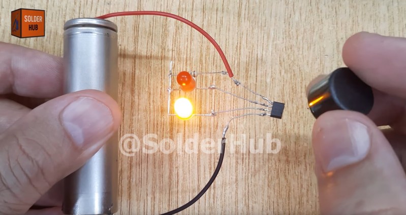
Recently, [Solder Hub] put together a brief video that demonstrates the basics of a Hall Effect sensor — in this case, one salvaged from an old CPU fan. Two LEDs, a 100 ohm resistor, and a 3.7 volt battery are soldered onto a four pin Hall effect sensor which can toggle one of two lights in response to the polarity of a nearby magnet.
If you’re interested in the physics, the once sentence version goes something like this: the Hall Effect is the production of a potential difference, across an electrical conductor, that is transverse to an electric current in the conductor and to an applied magnetic field perpendicular to the current. Get your head around that!
Of course we’ve covered the Hall effect here on Hackaday before, indeed, our search returned more than 1,000 results! You can stick your toe in with posts such as A Simple 6DOF Hall Effect ‘Space’ Mouse and Tracing In 2D And 3D With Hall Effect Sensors.


This is a good example of how not to use an 18650. It wouldn’t take much to short the positive wire to anywhere on the exposed case and give yourself a bad day.
Heatshrink is cheap.
Also, soldering wires directly to the cell is a no-no.
I bet you’re the kind of person who goes to parties and tells someone that pumping the keg too much creates foam.
dear god! i’m always so anxious when i am hooking up a lithium battery (usually soldering on its pigtails). but i only do it when i actually need a battery! if all i want is a bench supply for my experiments…i use my bench supply
treating a battery this way is such aggressively worst practices that i am now on the side of this should be banned from youtube, definitely not re-blogged by hackaday! there’s arguably a lot of value in showing the minimal reference circuit, but totally gratuitous danger as part of the demo is not just a little bit wrong. specifically for the people who wouldn’t automatically envision this demo in their head when they see the schematic at the end of the datasheet, this sets an example they might actually follow!
and to top it off, it’s not even an easy thing to do! any newbie attempting to play this same game at home after watching the video will find the step of trying to solder on a cell to be extra frustrating!
True ElectroBOOM engineering!
It’s just a demonstration of the function of the sensor don’t be that guy. Some people.
Wikipedia says exactly the same thing!
Yes it was a quote from Wikipedia! This fact got lost in the editorial process, sorry about that! Also it’s such a complex idea that I definitely wouldn’t try to put it in my own words for fear of getting it wrong!
Now that we know how the component works, we can use it in our own hacks.
Isn’t THAT what hackaday is about as well?
In order to start hacking, one first has to learn how the building blocks work.
Not everyone here is a pro or EE major.
While I can do more complicated projects, I also enjoy building small little gizmo’s like this occasionally. I was already wondering if I have one of these in my parts bin.
And I saw at least one small but useful hack: extend component leads to reuse an existing component.
It always gets me how the Hall effect has developed since its discovery.
The first experiments that proved its existence took a lab full of expensive equipment, expensive materials, and a bunch for folks in lab jackets all working together to make it work. From that, we’ve gone to a dinky little three pin gizmo that works reliably, every time, with no more fuss than a light switch. You’ve got Hall effect sensors that can provide an off/on signal for magnet/no magnet or sensors that can provide an analog output voltage proportional to the current flowing in a nearby wire. I’ve got an go-kart accelerator pedal that provides a 0-5V analog signal proportional to the distance the pedal is pressed. It uses a magnet on the pedal and a Hall effect sensor to detect the travel distance.
The main effect was discovered in the 19th century, and it was fairly simple to detect with a galvanometer of the time. Hall put a strip of foil the shape of a cross on a glass slide, connected the galvanometer on the two opposing branches, and passed current through the other two. The galvanometer would read zero when no magnetic field was present, and not-zero when a magnet was passed over the cross. This is an experiment one can repeat in school physics class, with some preparation.
The effect was theorized before, but could not be shown by experiment until they figured to use gold leaf for the metal, so it was thin enough to show a measurable difference. The thinner you make it, the better it works. Nowadays, if you wanted to make the demo, you would use something like a piece of ITO conductive glass (taken out of a touch screen).
https://web.physics.utah.edu/~lebohec/P5510/References/Discovery_of_Hall_effect.pdf
thank you!
your description reminds me the first time i tried to figure out how a cavity magnetron works. i looked at the circuit and said “i don’t get it, it’s a dead short.” the fact that you can (by using a magnetic field) develop a potential difference across a dead short is pretty neat!
Thanks for this, Dude. It was informative and interesting and I didn’t have to go anywhere else to learn it :)
I appreciate this kind of videos. Always learn something new
For instance this video taught me 4 pin hall effect sensors exist too!
Get a life.
Since it would seem that AI generated voiceovers are used everywhere these days, I wish that content creators would take a bit more time to proof the result.
The script clearly contained then words “…solder the positive pin (anode) to the…”, which the AI dutifully read verbatim. However a human would have said “…solder the positive pin, or anode, to the…” which sounds far more natural.
No matter how much I’m enjoying the content itself, errors like this pull my attention and distract from what’s being communicated
I have to agree with you 100%.
Yup. We’re going through the honeymoon phase with this new tool. People are overusing it to their detriment, just because they can.
But totally agree that it’s distracting, lazy, and ends up just feeling empty when compared to a real human narration. It’s going to look dated in another year or two.
That’s why we don’t do AI here.
The I guess AI narration can be understood – many of today’s videos are done by people with a thick accent that is so bad I can’t understand what is said, I could understand this narration
Wouldn’t a solder-less breadboard been easier? With a couple of clip leads for a “switch”?
I used MANY Hall effect sensors in interactive museum exhibits. They let me sense and identify plastic parts on a moving conveyer belt. They replaced mechanical switches in many applications. No grubby fingers getting into contacts, no wear.
Since I typically read them with a microcontroller, I often opted for analog output types. I could read them with an ADC and decide, at any time, what voltage represented the “threshold value”. This let me build my controller far ahead of the mechanical and cabinet bits, knowing I could adjust to whatever the final build magnet-to-sensor distance would be be.
You can do some fun tricks like back-biasing a sensor by positioning (gluing) a piece of steel to the back (use those screw cutter holes on your crimping tool to cut off a piece). This concentrates the flux through the sensor, increasing sensitivity.
A North Pole to one side of the sensor has the same effect as a South Pole to the other. Some switch on only when the magnet is present. Other latch on with one polarity and off with the other.
All in all they a very fun and useful components!
Ironically I first used them as bought from RS many years earlier. I still have one here. They were made by Sprague. Allegro took over the process around the latter part of the 1990s. I have a batch of them here. And yes that demo is just plain dangerous.