[Slant 3D] has a useful video explaining some thoughtful CAD techniques for designing 3D printed pins that don’t break and the concepts can be extended to similar features.
Sure, one can make pins stronger simply by upping infill density or increasing the number of perimeters, but those depend on having access to the slicer settings. If someone else is printing a part, that part’s designer has no actual control over these things. So how can one ensure sturdier pins without relying on specific print settings? [Slant 3D] covers two approaches.
The first approach includes making a pin thick, making it short (less leverage for stress), and adding a fillet to the sharp corner where the pin meets the rest of the part. Why? Because a rounded corner spreads stress out, compared to a sharp corner.
Those are general best practices, but there’s even more that can be done with microfeatures. These are used to get increased strength as a side effect of how a 3D printer actually works when making a part.
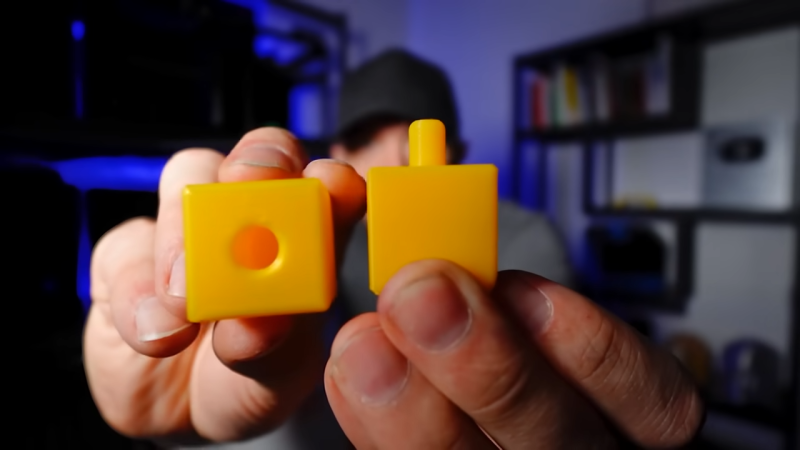
One type of microfeature is to give the pin a bunch of little cutouts, making the cross-section look like a gear instead of a circle. The little cutouts don’t affect how the pin works, but increase the surface area of each layer, making the part stronger.
A denser infill increases strength, too. Again, instead of relying on slicer settings, one can use microfeatures for a similar result. Small slots extending down through the pin (and going into the part itself) don’t affect how the part works, but make the part sturdier. Because of how filament-based 3D printing works, these sorts of features are more or less “free” and don’t rely on specific printer or slicer settings.
[Slant 3D] frequently shares design tips like this, often focused on designing parts that are easier and more reliable to print. For example, while printers are great at generating useful support structures, sometimes it’s better and easier in the long run to just design supports directly into the part.


I saw this a couple weeks ago and learned a bunch from it: some really useful ideas that I’d never seen before. Decent presentation style, too. Now let’s get it as a webpage rather than a video!
Nice. What software were you using?
Easiest approach: design in a hole (slightly tapered for best results) and sink in a self-tapping screw. Unbeatable strength.
The microfeatures that plunge all the way through the part instead of starting on the surface is a pretty clever idea, gonna steal that
anything that says perfect tolerances and unbreakable is 210% clickbait. Some nice ideas but the title is complete BS, but that is what you have to do to get the youtube and HAD algorithm clicks any more, it really sucks to be honest
+1
unbreakable and plastic is an impossible combination, this method is just a way to make brittle things a little bit harder to break, it’ll break. If you want something that doesn’t break, enforce it with screws or don’t use plastic in the first place.
Simple: don’t.
Not that you can’t, and this may be useful in some applications, but it still doesn’t solve the issue of the fact that you will inevitably have a stress riser at the root of the pin which is compounded by the layered nature of the print.
While this my be suitable for some applications, it’s just as easy to add a hole for a precision pin. Tolerancing for a press fit of the pin is also quite easy, especially when most printed materials will deform slightly when the pin is pressed into place. I find this method to be super effective and foolproof.
Regarding the question: “So how can one ensure sturdier pins without relying on specific print settings?”
Ehmm… upload the GCODE instead of the STL, this way the infill parameters have already been processed by the slicer at the GCODE generating end. No matter how you make it how how you design it, people will always be able to screw things up, if you keep fixing this in advance for them, they will never learn.
Just print it hot with PETG so layer lines don’t matter. Problem solved.