How To Avoid Failed Screw Holes In 3D Printed Parts

Screws are useful fasteners for 3D prints, but the effectiveness of a screw (not to mention the ease or hassle of insertion) depends on the hole itself. This comprehensive guide on how to design screw holes in 3D printed parts takes guesswork out by providing reference tables as well as useful general tips.

The guide provides handy tables saying exactly how big to design a hole depending on screw type, material (PLA, PETG, or high-flow PETG) and whether the hole is printed in a vertical or horizontal orientation. This takes the guesswork out of screw hole design.

There’s no reason to guess the right size of hole for a screw, just refer to some handy tables.

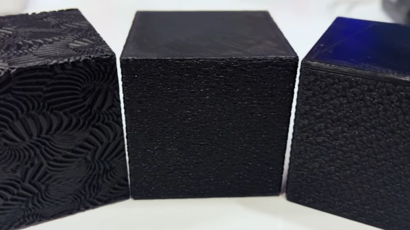
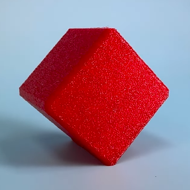
The reason for different numbers is because multiple (but predictable) variables affect a 3D-printed hole’s final dimensions. Shrinkage, filament properties, and printing orientation can all measurably affect small features like screw holes; accounting for these is the difference between a good fit, and cracking or stripping.

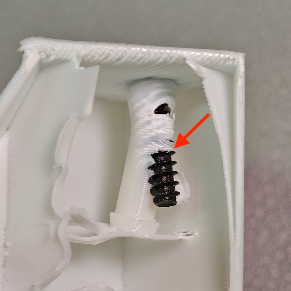
In addition to the tables, there are loads of other useful tips. Designing lead-ins makes screws easier to insert and engage, and while increasing walls is an easy way to add strength it’s also possible to use 3D-printed microfeatures which are more resistant to distortion and don’t depend on slicer settings. There’s even suggested torque amounts for different screw and material types.

Sure, the most reliable way to get a hole of a known size is to drill it out yourself. But that’s an extra step, and drill bits aren’t always at hand in the desired sizes. The guide shows that it is entirely possible to print an ideal screw hole by taking a few variables into account.

If your design calls for screws, be sure to check it out and see if there’s anything you can use in your own designs.

Christmas Ornament Has Hidden Compartment, Clever Design

If you need something clever for a gift, consider this two-part 3D-printed Christmas ornament that has a small secret compartment. But there’s a catch: the print is a challenging one. So make sure your printer is up to the task before you begin (or just mash PRINT and find out).

Want a challenging print that’s also useful? This two-piece ornament has a small gift area inside, and prints without supports.

This design is from [Angus] of [Maker’s Muse] and it’s not just eye-catching, but meticulously designed specifically for 3D printing. In fact, [Angus]’s video (embedded under the page break) is a great round-up of thoughtful design for manufacture (DFM) issues when it comes to filament-based 3D printing.

The ornament prints without supports, which is interesting right off the bat because rounded surfaces (like fillets, or a spherical surface) facing the build plate — even when slightly truncated to provide a flat bottom — are basically very sharp overhangs. That’s a feature that doesn’t generally end up with a good surface finish. [Angus] has a clever solution, and replaces a small section with a flat incline. One can’t tell anything is off by looking at the end result, but it makes all the difference when printing.

There are all kinds of little insights into the specific challenges 3D printing brings, and [Angus] does a fantastic job of highlighting them as he explains his design and addresses the challenges he faced. One spot in particular is the flat area underneath the hang hole. This triangular area is an unsupported bridge, and because of its particular shape, it is trickier to print than normal bridges. The workable solution consists of countersinking a smaller triangle within, but [Angus] is interested in improving this area further and is eager to hear ideas on how to do so. We wonder if he’s tried an approach we covered to get better bridges.

Want to print your own? 3D files are available direct from [Angus]’s site in a pay-what-you-like format. If your 3D printer is up to it, you should be able to make a few before Christmas. But if you’d prefer to set your sights on next year with something that uses power and hardware, this tiny marble machine ornament should raise some eyebrows.

Continue reading “Christmas Ornament Has Hidden Compartment, Clever Design”

How To Design 3D Printed Pins That Won’t Break

[Slant 3D] has a useful video explaining some thoughtful CAD techniques for designing 3D printed pins that don’t break and the concepts can be extended to similar features.

Sure, one can make pins stronger simply by upping infill density or increasing the number of perimeters, but those depend on having access to the slicer settings. If someone else is printing a part, that part’s designer has no actual control over these things. So how can one ensure sturdier pins without relying on specific print settings? [Slant 3D] covers two approaches.

The first approach includes making a pin thick, making it short (less leverage for stress), and adding a fillet to the sharp corner where the pin meets the rest of the part. Why? Because a rounded corner spreads stress out, compared to a sharp corner.

Continue reading “How To Design 3D Printed Pins That Won’t Break”

Stack N’ Rack Your Hardware With The HomeRacker Project

Things are cooler when rack-mounted, and [KellerLab] aims to make that all far more accessible with the HomeRacker, a modular and 3D-printable rack building system designed to let you rack-mount to your heart’s content. While it can handle big things, it seems especially applicable to tasks like mounting one’s home network equipment and Raspberry Pi machines.

A rack is a great place for those Raspberry Pi servers and home networking equipment, but it can also handle bigger jobs.

The basic system (or core) consists of three different parts: supports, connectors, and lock pins. The supports are the main structural bars, the connectors mostly go at the corners, and the lock pins ensure everything stays put. The nominal sizing is a 15 mm x 15 mm profile for the supports, with lengths being a multiple of 15 mm.

All is designed with 3D printing in mind, and requires no tools to assemble or disassemble. There are design elements we really appreciate, like how parts are printed at an angle, which improves strength while eliminating the need for supports. The lock pins (and the slots into which they go) are designed so that they are effective and will neither rattle nor fall out.

But the core system is just the foundation. There’s plenty of modularity and expansions to handle whatever one may need, from Gridfinity shelves and drawers to various faceplates and other modules. There are some example applications available from [KellerLab]’s HomeRacker models page, like CD shelf, under-desk drawer, or filament rack.

[KellerLab] welcomes any collaboration, so check out the GitHub repository for CAD references and design files.

One last point to make about the value of printing objects like this at an angle: not only can the resulting layer lines provide better strength and reduce or eliminate the need for supports, but printing at an angle can help hide layer lines.

Continue reading “Stack N’ Rack Your Hardware With The HomeRacker Project”

Would An Indexing Feature Benefit Your Next Hinge Design?

[Angus] of Maker’s Muse has a video with a roundup of different 3D-printable hinge designs, and he points out that a great thing about 3D printing objects is that adding printable features to them is essentially free.

These hinges have an indexing feature that allows them to lock into place, no additional parts needed.

A great example of this is his experimental print-in-place butt hinge with indexing feature, which is a hinge that can lock without adding any additional parts. The whole video is worth a watch, but he shows off the experimental design at the 7:47 mark. The hinge can swing normally but when positioned just right, the squared-off pin within slots into a tapered track, locking the part in place.

Inspired by a handheld shopping basket with a lockable handle, [Angus] worked out a design of his own and demonstrates it with a small GoPro tripod whose legs can fold and lock in place. He admits it’s a demonstration of the concept more than a genuinely useful tripod, but it does show what’s possible with some careful design. Being entirely 3D printed in a single piece and requiring no additional hardware is awfully nice.

3D printing is very well-suited to this sort of thing, and it’s worth playing to a printer’s strengths to do for pennies what one would otherwise need dollars to accomplish.

Want some tips on designing things in a way that take full advantage of what a 3D printer can achieve? Check out printing enclosures at an angle with minimal supports, leveraging the living hinge to print complex shapes flat (and fold them up for assembly), or even print a one-piece hinge that can actually withstand a serious load. All of those are full of tips, so keep them in mind the next time you design a part.

Design Tips To Hide Layer Lines In 3D Printed Parts

[Slant 3D] knows a lot about optimizing 3D prints so that they can be cranked out reliably with minimal need for post-processing, and in this short video he uses a cube as a simple example of how a few design changes can not only optimize for production, but can even hide layer lines pretty effectively.

Just to be perfectly clear, layer lines cannot be eliminated entirely without some kind of post-processing. But [Slant 3D]’s tips sure goes a long way toward making a part lose that obvious 3D-printed “look”. They also dovetail nicely with advice on how to optimize cranking out high numbers of parts in a print farm.

Adding texture to the outer layer is especially effective when combined with non-traditional part orientations.

One simple way to avoid visible layer lines is to put some kind of texture onto the part. This can be modeled into the part’s surface, or the slicer software can be used to modify the exterior of the print to add a texture such as a geometric pattern or by applying a fuzzy skin modifier.

Printing a texture onto the exterior is great, but the outcome can be even further improved by also printing the object in a non-traditional orientation.

Using a cube as an example, printing the cube on a corner has the advantage of putting the layer lines in a different orientation as well as minimizing the contact area on the print bed. This applies the texture across more of the part, and looks less obviously 3D printed in the process. Minimizing bed adhesion also makes parts much easier to remove, which has obvious benefits for production. [Slant 3D] points out that performing these operations on a 3D-printed part is essentially free.

A few other optimizations for production involve rounding sharp corners to optimize tool travel paths, and putting a slight chamfer on the bottom of parts to avoid any elephant foot distortion (Elephant’s foot can be compensated for, but simply putting a slight chamfer on a part is a design change that helps avoid accounting for machine-to-machine variance.)

Even if one has no need to optimize for high production volume, the tips on hiding layer lines with design changes is great advice. Watch it all in action in the short video, embedded below.

Continue reading “Design Tips To Hide Layer Lines In 3D Printed Parts”

Lessons In Mass Production From An Atari Punk Console

Sometimes the most interesting part of a project isn’t the widget itself, but what it teaches you about the manufacturing process. The story of the manufacturing scale-up of this Atari Punk Console and the lessons learned along the way is a perfect example of this.

Now, don’t get us wrong — we love Atari Punk Consoles. Anything with a couple of 555s that bleeps and bloops is OK in our books. But as [Adam Gulyas] tells the tale, the point of this project was less about the circuit than about the process of making a small batch of something. The APC was low-hanging fruit in that regard, and after a quick round of breadboarding to decide on component values, it was off to production. [Adam] was shooting for 20 units, each in a nice enclosure and a classy package. PCB assemblies were ordered, as were off-the-shelf plastic enclosures, which ended up needing a lot of tweaking. [Adam] designed custom labels for the cases, itself a fraught job; glossy label stock and button bezels apparently don’t mix.

After slogging through the assembly process, boxing the units for shipping was the next job. [Adam] sourced jewelry boxes just a bit bigger than the finished APCs, and rather than settle for tissue paper or packing peanuts, designed an insert to hold the units snugly. That involved a lot of trial and error and a little bit of origami-fu, and the results are pretty nice. His cost per unit came out to just a hair over $20 Canadian, including the packaging, which is actually pretty remarkable for such a short production run.

[Adam] includes a list of improvements for larger-scale runs, including ordering assembled PCBs, outsourcing the printing processes, and getting custom boxes made so no insert is needed. Any way you cut it, this production run came out great and teaches us all some important lessons.