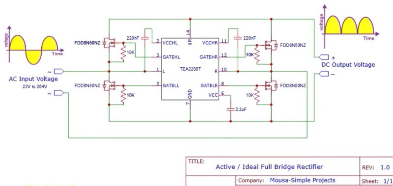
Everyone loves a full-wave bridge rectifier, but there’s no denying that they aren’t 100% efficient due to the diode voltage drop. Which isn’t to say that with some effort we cannot create an ideal bridge rectifier using active components, as demonstrated by [Mousa] with an active bridge circuit. This uses the NXP TEA2208T active bridge rectifier controller, along with the requisite four MOSFETs.
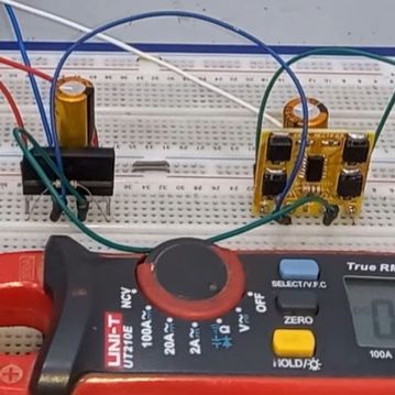
Taking the circuit from the datasheet, a PCB was created featuring four FDD8N50NZ MOSFETs in addition to the controller IC. These were then compared to a diode-based bridge rectifier, showing the imperfections with the latter when analyzing the output using an oscilloscope.
As expected, the active rectifier’s output was also one volt higher than the diode bridge rectifier, which is another small boost to overall efficiency. According to NXP’s product page, there’s about a 1.4% efficiency gain at 90 VAC, with the chip being promoted for high-efficiency operations. When you consider that many designs like computer PSUs feature one or more diode bridge rectifiers often strapped to heatsinks, the appeal becomes apparent. As for [Mousa], he put this particular board in his laboratory PSU instead of the diode bridge rectifier, because why not.
Perhaps the biggest impediment to using an active rectifier is the cost, with the TEA2208T coming in at $4 on DigiKey for a quantity of 100, in addition to the MOSFETs, PCB, etc. If power efficiency isn’t the goal, then some wasted power and an aluminium heatsink is definitely cheaper.


A single video by Boxxy wastes more energy than basic rectifier over its entire lifetime.
That nerd burn is so sick it heats the PCB until all components are dropping off.
(The tin fumes are a bonus sick “burn” to the nostrils.)
Not sure if there’s any substance to it but whatever.
“Perhaps the biggest impediment to using an active rectifier is the cost, with the TEA2208T coming in at $4 on DigiKey for a quantity of 100, in addition to the MOSFETs, PCB, etc.”
Any company using this can just raise their prices and say, it’s the tariffs. Problem solved.
Ok NXP, why no datasheet? No PDF with useful info, no sale. And the product would be interesting too, I would like to maybe make a bench supply with something like this. I am curious if it does SMPS active rectification.
What are you talking about? It’s linked right on the product page.
https://www.nxp.com/docs/en/data-sheet/TEA2208T.pdf
Click on “Documentation” at the page the link in the text brings you (https://www.nxp.com/products/power-management/ac-dc-solutions/ac-dc-controllers/full-wave-active-bridge-rectifier-controller:TEA2208T)
Depending on how some “ideal diodes” are implemented, they can have interesting and sometimes dramatic failure modes, like holding a switch (“diode”) closed when the source power is removed but the load power is still present (like a battery charger).
A quick perusal of the data sheet doesn’t reveal how this IC behaves in cases like that. It appears that when input AC power is removed the control circuitry turns off all the MOSFET gates, but it also looks like it requires the load voltage to disappear too in order for this to happen.
It also requires a curious 0.45-second reset period after power removal to reset and restart normally. What happens if that constraint is not satisfied, like everyday mains power glitches that remove power for a cycle or two during utility switchgear changes?
It merits some extra testing before building this into a product, especially if you’re doing something unusual like redundant or multiple supplies, battery backup, battery charging, etc.
It’s worse. If it isn’t specified, they are free to change it during production run, i.e. give you a different product bearing the same name, but with different behavior.
Some pinball games flash their playfield illumination lights (connected to 6.3VAC) with a relay. I have been looking for a clickless solution without voltage drop, but it looks like a relay is still king.
You could use an SSR for that.
In the absence of details, I would think a triac is the obvious solution.
Not at 6.3V AC, Triacs have >1V voltage drop. Same goes for SCR- and Triac-based SSRs.
There are an awful lot of optorelays that will do that. For example, a TLP170 drops less than a tenth of a volt at 0.3A, for much less than a couple of bucks.
Something like that. But the lamps operate on AC and take almost 10A. (there are lots of #44 bulbs @250mA each).
A photorelay switches AC, no problem.
If you don’t find one that can handle the current you need, put some in parallel. Or put one per lamp base.
Or roll your own FET-based solution. This is not a hard problem.
Try feeding DCV to a spare lamp sometime.
Also, if the 6v3 transformer is supplying just lamps. switch it’s input (mains line voltage, at a much lower total current) using a triac or SSR.
I don’t service pinball or arcade machines, perhaps there’s some reason this isn’t feasible, but if you’re running even a US 120Vrms input to a 6v3rms out, a 1V reduction in the input voltage is absolutely within variance in grid voltage, assuming the output voltage isn’t actively regulated, you’re looking at 6.2475V with that 1V drop in input. A gnat’s sneeze more than 50mV
Glasstube filled with mercury, rotate it.
Triac or SSR would sort of work, but the voltage drop would be too much to keep 6.3V lamps at normal brightness. Maybe two anti parallel connected MOSFETs could work, but then driving them is not going to be easy.
You can drive “two antiparallel MOSFET’s” with an isolated DC-DC converter. It’s a bit over the top, but because these things are cheap COTS, it’s still a viable solution. And there are also optomos IC’s that are designed for driving external FET’s.
Or just buy a single 4-pin part that’s designed for the job. The TLP170A I mentioned above can switch a half amp. Its bigger brother the TLP3555A will handle more than two amps, still less than $3 in onesies. Not enough? Parallel them. They’re FETs. They’ll happily curent-share.
The ‘ideal diode’ concept, and its design and its usage is most definitely not new; it’s as old as the operational amplifier (op-amp) itself.
There are places in electrical engineering design for the ideal diode makes imminent sense.
This is not one of them.
This chip has a minimal start voltage of 9V. What can I use for active rectification of the output of a bicycle dynamo?
I googled “low voltage synchronous rectifier” and one result was the UCC24630, Vdd = 3.6 V to 28 V.
Another concept to steer your search would be energy harvesting, because you also have to regulate that voltage or use it to top up a battery.
Since the chip uses very little power, you might just feed a capacitive voltage doubler with a bridge rectifier.
The UCC24630 is unfortunately designed to replace just the one diode on the secondary side of a flyback converter.
6V bicycle dynamo sorts out 6Vac !
So why not put two dynamos in series ;-? One at each side of the tyre.
OR, with a simple voltage doubler-rectifier, you get the same power, but twice the voltage.
Beware, power remains the same, so half the current ;-)
But not with two dynamos in series, you’ll get double voltage, and double power !
Regards, harry.
I’m pretty sure that this does not work at all with the schematic provided. The 10k pull downs on the gate are too much for the 220nF cap to overcome at low frequencies. The reference schematic in the datasheet does not show any pull down resistors for a reason.
Iamalas, the 220nF’s are the High-side Bootstrap capacitors !
It is merely an inverted use of a full H-bridge.
The 10K ohm Gate-source resistors are to make sure MOSFETS are off when not driven.
It is maybe a nice conceptual idea, for plain resistive Loads, . . .
But, what happens when there is phase shift between Current and Voltage due to
the Loads inductive or Capacitive nature ;-?
Anyone going to mention rhe risks playing with live voltages and 400V DC bus? I would add that to the « main impediments ».
Designing and integrating a board like this in a safe manner requires a good understanding of the risks and safeguards necessary (both for development/validation and for usage).
Have fun but stay safe!
I don’t think this chip can be operated with a bulk capacitor directly behind the bridge.According to the scarce information in the data sheet , it operates 2 mosfets at teh same time diagonally depending on the direction of the voltage slope at the input. It’s voltage controlled , and doesnot sense any current flowing back from the bulk capacitor to the AC source.
Hi folks, I too have my doubts on this added complexity, for the gain of a margin 1% efficiency ? ? ?
I truly think: this is maybe perhapse only viable for Low voltage battery operated parts.
Because Shottky’s have one major drawback:
and that is their inherent High reverse current flow of milli Amps !
But on high amplitude AC-mains, there is no significant gain.
Only additional components that can fail.
Moreover, it is merely an invert use of a full H-bridge.
Where the synchronisation comes from the zero-crossings.
So what happens, with Voltage-vs-Current phase shifts, due to Loads inductive or capacitive behaviours ?!
And complete kits, EVMs, are sold really expensive ? ? ?
Common, Homo-sapiens, you can do better ;-)
Regards, Harry.
Hi folks, I too have my doubts on this added complexity,
for the gain of a margin 1% efficiency ? ? ?
I truly think: this is maybe perhapse only viable for Low voltage battery operated parts.
Because Schottky’s have one major drawback:
and that is their inherent High reverse current flow of milli Amps !
But on high amplitude AC-mains, there is no significant gain.
Only additional components that can fail.
Moreover, it is merely an invert use of a full H-bridge.
Where the synchronisation comes from the zero-crossings.
So what happens, with Voltage-vs-Current phase shifts,
due to Loads inductive or capacitive behaviours ?!
And complete kits, EVMs, are sold really expensive ? ? ?
Common, Homo-sapiens, you can do better ;-)
Regards, Harry.