When you’re testing or debugging some mains-powered gear, plugging it directly into the outlet can often be an exciting proposition. If such excitement is not really your thing, you can opt for an isolation transformer and other types of safeties. In the case of [Michał Słomkowski], he opted to take a few steps further by modding a vintage East-German isolating variac with a broken amp meter into an isolated AC/DC power supply and testing station.
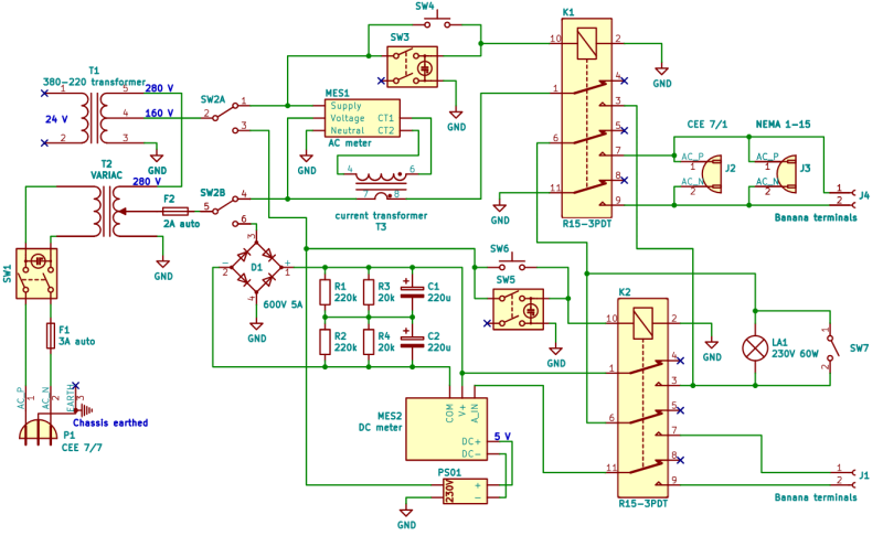
The core is formed by the isolated variable transformer, to which a configurable DC output section, a current limiter and digital voltage and current read-outs were added. This enables a variable AC output of 0 – 330 VAC and 0 – 450 VDC on their respective terminals, with the incandescent light bulb providing an optional current limiter.
In its final configuration [Michał] has been using the device for the past four years now for a range of tasks, including the simulating of various undesirable mains power conditions, varying the speed of an old Soviet-era drill, powering vacuum tube devices, capacitor reforming and of course running 100-120 VAC devices from e.g. the US.
As far as feature set goes, we have to admit that it is an impressive device, indeed. Although some parts of it are clearly playing it fast and loose with best practices, with [Michał] admitting to not being an electrician, it was clearly engineered well enough to survive a few years of use, something which cannot be said for even professional laboratory equipment these days.


I’m no EE, and not even a good hobby-ist, but that schematic is a mess. While I get the intend of some parts, things just don’t click logically for me. Every corner I’m hmm, I think this is what it means, by then why …
Also the front panel is messy.
Having said that, I think it’s a great project and I couldn’t quite pull this off and I do like the retro? Style of the panel :)
Front panel messy? I mean, sure, it looks like the unholy child of Fisher Price and a Dymo machine, but the layout is decent.
Yeah, looking at it a second time, it’s really Nice, what threw me off is the fuses, those are the only two not in sync, the somehow stood out ..
o I stand corrected, really nice panel, except the misalginment on the fuses :p
This reminds me of something we looked at for a lab a while back.
The students had to test a lot of 240VAC stuff, but it was all really low power. They where doing some ethernet over powerline stuff I think.
I was looking for something that would provide an isolated 240VAC that was current limited to about 5mA. Couldn’t find anything off the shelf. I wonder is that still dangerous enough that no one can really sell it? It’s obviously easy enough to implement in principle with a 1:1 transformer and some currently limiting components.
Easiest way to do that for low power projects is to just put two small 240V-9V or 240V-12V transformers back to back, these can be easily scavenged from old boomboxes or found for a few bucks at your local electronics store.
Yeah, good advice, thanks.
It’s just that this was for a lab in a school, so something DIY for this sort of thing is usual off the table.
Interesting! SO you take two 240V-12V and put them into a (240V-12V)-(12V-240V) configuration? Isn’t there any diode that would prevent the current going between the two 12V part, especially the second one which has been reversed? Sorry for the daft question, I’m no EE as you can see
In the olden days, pre-GFCI/RCD, it was common to find “razor” outlets in bathrooms: These were quite small isolation transformers. They provided both isolation and power limiting (to about 50 watts).
I have not seen one in a long time. I wonder if they are even sold any more. They sure don’t appear in the local home improvement stores.
They are mandatory in the UK.
Concerning the schematic, shouldn’t there be a ground connection between R1 and R2?
Yeah, it’s just resistors in parallel?
But no ground there please. +/- are both floating and I think R1-R4 are there for two reasons:
A) make sure both caps C1 & C2 always have the same voltage across them (voltage divider)
B) bleed resistors to discharge the caps.
Doesn’t explain why there are 20k and 220k in parallel.
I have two comments regarding safety.
1: the fuse F1 is ins the Neutral line – totally wrong!
2: F1 and F2 are Auto fuses which, I believe, are rated for 32V – NOT 240V!!
1: You are totally wrong. There is no fixed neutral.
CEE 7/7 plugs can be plugged in either way in ~half the available receptacles.
-> You can never be sure which side is neutral or phase (or if both are floating).
2: Pretty sure they are available for higher voltages as well (I think I have some).
I think many small in-line UPSs have those – and not in the battery circuit.
I bought an isolated variable transformer back in July.
Most variable transformers are unisolated autotransformers. Like the one in this Hackaday article, mine is a truly isolated variable output transformer.
Odd critter that it is, I was quite happy I found it. You’d normally need two transformers to get an isolated variable output – an isolation transformer and a variac. Both of them would be rather heavy. With my Philips B870900/C3 isolated variable transformer, I only have to have one piece of heavy equipment of the workbench. Well, OK, two. I sill have my heavy old Telequipment D43 dual channel oscilloscope sitting there.
Philips isolated transformer:
https://josepheoff.github.io/posts/isolatedvariac
Telequipment D43 oscilloscope:
https://josepheoff.github.io/posts/d43toc
VS. (from the linked writeup)
So what is your claim based on? Even the schematic clearly shows an isolation transformer.
Yes, that’s what I said. Both my transformer and the one in this Hackaday article are true isolated variable transformers.
Doh! My bad, sorry.
Punctuation (comma instead of full stop) plus formatting (,/. at the end of the line) & you repeating the same fact in ~3 sentences lead to me “reading” this instead:
+
They still sell tapes for demo lable printers?
I haven’t seen it in stores around here for a long time, but you can still find it online if you search for “embossing label tape”.
I like the momentary push buttons in parallel to the normal switches. To test equipment you’re really not sure about.
The built in light bulb is a nice touch too – see http://www.repairfaq.org/sam/smpsfaq.htm#smpstslbt
Build my own “pretty-much” isolation transformer from two identical 230V-to-110V stepdown autotransformers (1 & 2).
Both have three taps: “neutral”, 110V and 230V
Splitting them at each “center” tap results in A: neutral-to-110V and B: 110V-to-230V
By putting each 1A+2B and 1B+2A in series I’ve got an isolation transformer split across two almost 1:1 transformers.
But this way the isolation isn’t conform to proper isolation norms. Kinda like badly designed PSU PCBs with too little distance between primary and secondary side: It works but if you get a a higher voltage glitch you may get “burned”. :-/
But I had nothing better to do with those two identical autotransformers.
I don’t understand the connection between K2 and K1. I don’t see purpose apart from maybe sharing LA1 (?) for DC and AC and it may even be harmful when K1 and/or K2 don’t turn off quickly enough.
As Oliver pointed out the schematic looks messy, which may not help with reading this part accurately.
Hello, author here.
The schematic indeed looks messy, that was is mainly because of 3PDT relay symbols available in KiCad. I didn’t feel the need to go extra mile to make my own symbol for it.
You’re right that the connection is make because of sharing LA1. I use all three contacts to break the path of the current in many places.
I did a quick check of the schematic for the hypothetical situation when both relays stay closed for some reason and both loads for AC and DC are connected. It seems, the variac would be shorted out by one of the diodes in the bridge rectifier and blow one of the fuses.
That interconnect is the only part of that fine(!) schematic I couldn’t decipher on 1st try.
But you bring up a good point – let me draw it further:
If both AC & DC were on at the same time (relays K1 & K2 active) it would be a whole lotta mess.
Now let me counter it: This ^^ can never happen because the main selector switch on the other side (SW2A+B) makes sure only one of K1/2 can be on at any given moment – never both.