
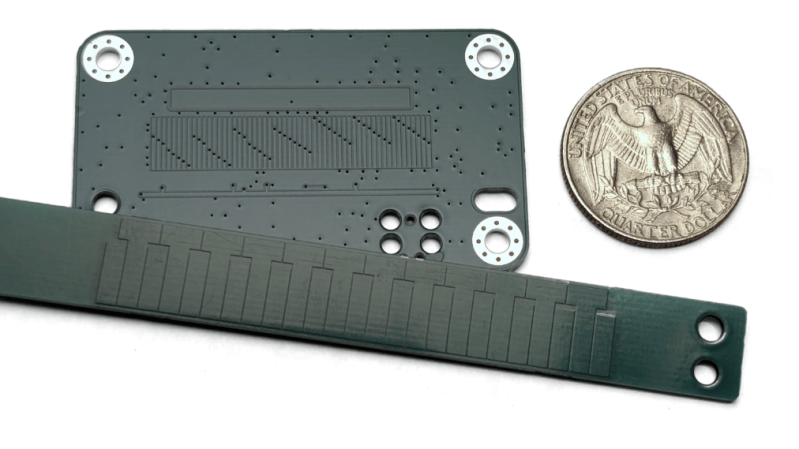
If you’ve ever pulled apart a set of digital calipers, you’ve probably marvelled at the capacitive encoder that does all the measuring work. There’s nothing stopping you from using the same techniques yourself, as [Nick] demonstrates with an open-source capacitive encoder of his own design.
The sensor PCB works by by having a grid of eight transmitting antennas, etched into a PCB, beneath a larger receiving antenna. The transmitting antennas pulse out a pattern as the sensor PCB moves, with the signals bouncing back from the reflector PCB which is fixed in place. The varying capacitance caused by the position of the reflector elements relative to the sensor PCB varies the strength of the pulses hitting the receiving antenna. A microcontroller—in this case an STM32—can read those pulses to determine the displacement of the sensor PCB relative to the reflector down to a very fine degree. In this case, to an accuracy of 40 micrometers. Not bad!
If you need ultra-fine linear tracking for something you’re building, you might find this project very useful. Files are available on Github for the curious, along with a great explainer on exactly how the capacitive coupling becomes a positional reading. You can also study previous teardowns we’ve featured on cheap digital calipers, just to round out your education further. If you’re working on your own impressive workshop equipment, or subcomponents of such things therein, don’t hesitate to let us know on the tipsline!











The reflector-PCB approach is a neat way to get the same trick digital calipers use without needing any custom silicon, and 40 micrometres from an STM32 and a few etched antennas is impressive. I’d be curious how much the readings drift with temperature or with a slightly tilted reflector, since calipers have very tight mechanical tolerances to lean on. The linked explainer on the capacitive coupling sounds like a great read for anyone who has taken a pair apart.
Thank you for this work!
I still think it’d be cool to slap these on 3d printers
Inkjet printers use an optical linear encoder to determine where the print head is. I’m surprised those didn’t end up in 3D printers.
Maybe using the sensor from an old flat bed scanner? 1200dpi seems like plenty of resolution.
most printers don’t have an actual absolute or relative encoder, they just have a single clock track. it allows them to synchronize the print head with the movement of the carriage but can’t be use to do closed-loop control of the carriage itself
I don’t agree. A simple linear incremental encoder is perfectly fine to create feedback for a closed loop controller. Most (simple) motor encoders are just a disk with lines at regular intervals. and the position can be tracked with a quadrature decoder, which is common in most modern microcontrollers (but can also be done in software if the speed is not too high). For a quadrature encoder, you need two sensors on the row of circle of lines, which have a (sort of) 90 degree phase shift.
Adding a linear sensor such as used in flatbed scanners to such an encoder gets you close to a “moire” scale. You can possible enhance the resolution with that.
A few months ago I did a short test by pointing a webcam at a regular measure tape (1mm increments) and had an ai dream up some python code to interpret the lines. My test suggested I could get a resolution of 10um or better, but of course not the accuracy.
Such a webcam can also read the numbers on the tape, so it can be used as an absolute scale too.
IIRC, precision steppers have a step angle, so you could probably calculate the position based on step angle and number of steps, making this redundant under normal circumstances for a 3d printer. The only thing it would really give you is a safeguard against belt slip/stretch and the like.
Would still be cool, though. :)
I´ve been 3d printing for more than 10 years by now, today is not such a problem, but at first, a stepper missing several steps meant loosing the print, closed loop steppers or servos retrofitted in 3d printers as experiments have proven to increase reliability but its expensive, i haven´t had a printer miss a step since the last 4 years maybe.
I’m far less familiar with the situation in 3d printers; but with conventional printers the move(whether for performance or just for cost reasons) was away from precision steppers and toward more ordinary motors plus position sensing(normally optical arrangements with a gray code printed on a disk to monitor rotation and a row of opaque stripes on a clear sheet to allow the print head to judge its travel back and forth).
Means you need a more sophisticated feedback loop system; and the motors you can scavenge aren’t nearly as nice as in the older printers that 100% depended on the steppers stepping as expected; but I suspect that running fairly high speed control loops is now sub 25 cent microcontroller stuff; while precision mechanical parts haven’t fallen in price nearly as much; so the logic works out, especially if you are stamping out 10 million of a given model.
This is epic.
I wonder if having the antenna side not with straight, but zigzag lines. In the latest log they were having a systemic error with the copper free gaps on the emitter side.
I think with the zigzags there never will be a copper gap lining up and thus no/less error? (something like: https://fab.cba.mit.edu/classes/863.19/Architecture/people/Alex/Week11/index.html)
(I tried commenting on the Log, but it didn’t let me)
The question that bothered me: what is the speed limit? is answered in the README:
“Conservatively, the maximum speed might be 0.6m/s, although I have not tested this.”
I’m curious if this can also be applied to rotary encoders? This technique seems to be able to provide very high angular resolution, at least at low speeds.
If you don’t need absolute positioning i don’t see why it wouldn’t work. sadly this type of capacitive sensing does tie up the mcu but might not be a deal breaker with dual core mcu.
Yeah looks like it should work. But until someone actually has working design files I’ll reserve my judgement. Sounds like a bit of research could be needed.
Re: processing power, I’d rather have a dedicated cheap MCU be an exclusive encoder controller, so it’s like a complete black box for my application. If a ch32v003 family MCU could do that it would be amazing.
It definitely can; I’ve seen commercial products that do this (including using a PCB as the elements).
Truly a marvel of engineering, but I’m wondering if you can also play Chopsticks on it.
I like this, but left wondering if there is any limit, other than PCB capability, on the length of the antenna section? Can shorter 0.5m lengths be added together in some way? I’ll ask GPT6.
Computer says Yes—roughly 0.5 m sections could be joined in principle. The difficult part is preserving the copper pattern and alignment across each joint. I found no specified maximum length, but also no documented test of a joined, metre-scale version.
Assuming by “antenna section” you mean the long stationary strip, the project calls that the reflector. It is passive; the transmitters, receiver and electronics sit on the moving readhead. The author explicitly describes extending the reflector by repeating its pattern every 5.08 mm (200 mil). Hardware documentation
That means there is no obvious electrical limit tied directly to total strip length: my engineering inference is that the readhead primarily interacts with the pattern immediately beneath it. You would not need to carry the sensing signal electrically along the entire rail.
Joining sections would need a deliberately designed joint:
– Maintain the pattern spacing across the seam. For identical modules, choose a module-to-module spacing that is a whole multiple of 5.08 mm—for example, 497.84 mm = 98 repeats. Exactly 500 mm does not meet that condition. Include any physical joint gap when calculating that spacing.
– Place the seam between complete copper features. Extra blank board margins, missing features or a large gap would disturb the measurement while the head crosses. The reflector sections should not need signal wiring between them; their patterned surfaces need to align.
– Keep the surfaces flush and straight. A common rigid backing with precise locating features would help. The nominal readhead-to-reflector gap is only 0.1 mm, so a step between boards matters. The author has not yet quantified sensitivity to gap, sideways offset or tilt. Mechanical integration
Those joint suggestions are an engineering proposal, not a tested assembly method supplied by the project.
Other practical limits remain:
– Thermal expansion and dimensional accuracy. As an illustration, Isola FR408HR specifies an in-plane expansion of 16 ppm/°C: an unconstrained 1 m length changes by 160 µm over 10°C. Your actual laminate and mounting would determine the result. That already exceeds the project’s quoted 40 µm electrical accuracy, so that figure should not be treated as a guaranteed accuracy over a long rail. Isola datasheet
– Continuous tracking. This is an incremental encoder. A sufficiently bad seam could cause a position error or lost period count, which can persist after crossing it. Operating principle
– End allowance. The sensing grid is 30.48 mm long and must remain fully covered. Usable travel is therefore patterned length minus 30.48 mm, before mounting allowances. Reflector dimensions
I would first prototype one joint using two short sections, then measure repeated crossings in both directions against an independent reference. If a sufficiently clean joint is impractical, two readheads spaced so that only one crosses a seam at a time could provide a handover—but that would require additional electronics, calibrated offsets and firmware changes.