
Around these parts, projects needlessly using a microcontroller where a simpler design would do are often derided with the catch-all “Should have used a 555,” even if the venerable timer chip wouldn’t have been the ideal solution. But the sentiment stands that a solution more complicated than it needs to be is probably one that needs rethinking, as this completely mechanical chaser light badge Simple Add-On (SAO) aptly demonstrates.
 Rather than choosing any number of circuits to turn a strip of discrete lights on and off, [Johannes] took inspiration for his chaser lights from factory automation mechanisms that move parts between levels on steps that move out of phase with each other, similar to the marble-raising mechanism used in [Wintergatan]’s Marble Machine X.
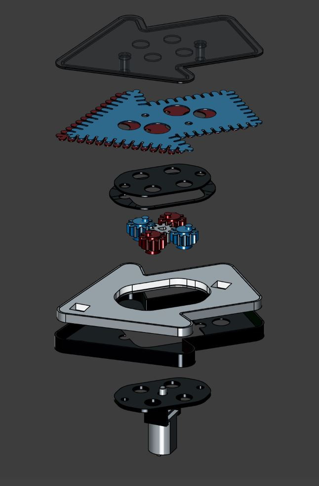
Two thin plates with notches around the edge are sandwiched together inside the 3D printed case of the SAO, between the face and the light source. A small motor and a series of gears rotate the two masks 180° out of phase with each other, which creates the illusion that the light is moving.
It’s pretty convincing; when we first saw the video below, we were sure it was a row of tiny LEDs around the edge of the badge.
Hats off to [Johannes] for coming up with such a clever mechanism and getting it working just in time for Hackaday Europe. If you need to catch up on the talks, we’ve got a playlist ready for you.
Continue reading “Chase Light SAO Shouldn’t Have Used A 555, And Didn’t”


