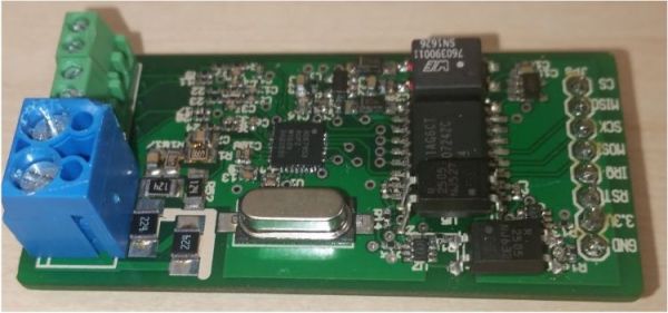
There are many reasons why one would want to measure voltage and current in a project, some applications requiring one to measure mains and even three-phase voltage to analyze the characteristics of a device under test, or in a production environment. This led [Michael Klopfer] at the University of California, Irvine along with a group of students to develop a fully isolated board to analyze both single and three-phase mains systems.
Each of these boards consists out of two sections: one is the high-voltage side, with the single phase board using the Analog Devices ADE7953 and the three-phase board the ADE9708. The other side is the low-voltage, isolated side to which the microcontroller or equivalent connects to using either SPI or I2C. Each board type comes in either SPI or I2C flavor.
Each board can be used to measure line voltage and current, and the Analog Devices IC calculates active, reactive, and apparent energy, as well as instantaneous RMS voltage and current. All of this data can then be read out using the provided software for the Arduino platform.
The goal of this project is to make it easy for anyone to reproduce their efforts, with board schematics (in Eagle format) and the aforementioned software libraries provided. Here it is somewhat unfortunate that the documentation can be somewhat incomplete, with basic information such as input and measurement ranges missing. Hopefully this will improve over the coming months as it does seem like a genuinely useful project for the community.
We’ve covered the work coming out of [Michael]’s lab before, including this great rundown on Lattice FPGAs. They’re doing machine vision, work on RISC-Vchips, and more. A stroll through the lab’s GitHub is worth your time.


