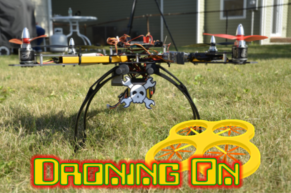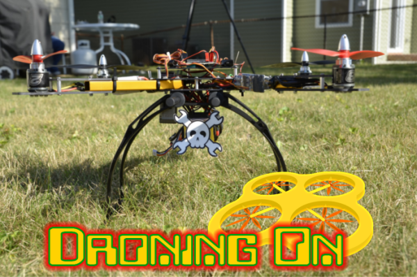
When we last left off, the Hackaday Drone Testbed was just a box of parts on workbench. Things have changed quite a bit since then! Let’s get straight to the build.
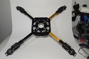
With the arms built and the speed controls soldered up, it was simply a matter of bolting the frame itself together. The HobbyKing frame is designed to fold, with nylon washers sliding on the fiberglass sheets. I don’t really need the folding feature, so I locked down the nylock nuts and they’ve stayed that way ever since. With the arms mounted, it was finally starting to look like a quadcopter.

Using the correct screws, the motors easily screwed into the frames. I did have to do a bit of filing on each motor plate to get the motor’s screw pattern to fit. The speed controls didn’t have a specific mount, so I attached them to the sides of the arms with double-sided tape and used some zip ties to ensure nothing moved. In hindsight I should have mounted them on the top of the arms, as I’m planning to put LED light strips on the outside of edges of the quad. The LEDs will help with orientation and ensure a few UFO sightings during night flights.
Power distribution is a major issue with multicopters. Somehow you have to get the main battery power out to four speed controls, a flight controller, a voltage regulator, and any accessories. There are PCBs for this, which have worked for me in the past. For the Hackaday Testbed, I decided to go with a wiring harness. The harness really turned out to be more trouble than it was worth. I had to strip down the wires at the solder joint to add connections for the voltage regulator. The entire harness was a bit longer than necessary. There is plenty of room for the excess wire between the main body plates of the quad, but all that copper is excess weight the ‘bench’ doesn’t need to be carrying. The setup does work though. If I need to shed a bit of weight, I’ll switch over to a PCB.
Click past the break to read the rest of the story.


