Microchip ICD4 REview

[Mike] is an avid PIC developer and replaced his ICD3 debugger for an ICD4. He made a video with his impressions and you can see it below. [Mike] found the heavy aluminum case with a sexy LED attractive, but wondered why he was paying for that in a development tool. He was also unhappy that they replaced the ICD3 cable connections with new connectors. Finally, he wished for the pin out to be printed on the case.

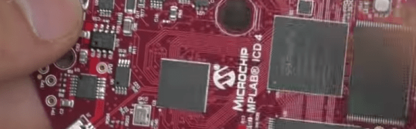
On the other hand, the ICD4 will also do JTAG and handle the Atmel parts (which Microchip acquired). [Mike] opens the box and shows the inside of the device before actually using it for the intended task.

Continue reading “Microchip ICD4 REview”

Making The Case For In-circuit Debugging Tools

in_circuit_debugging_of_pic_microcontrollers

If you are in the market for a PIC microcontroller programmer, you may want to consider a model with an In-Circuit Debugger (ICD). [Rajendra] put together a great tutorial on using an ICD when debugging PIC firmware, which makes a pretty convincing argument for owning one.

In his tutorial, he happens to be using a MikroElektronika PICflash2, but he says that there are plenty of other ICDs out there if you are not keen on this particular model. The PICflash2 not only acts as an ICD, but as the name suggests it works as an ICSP as well.

[Rajendra] walks us through a short debugging session using some simple code that reads data from an LM34DZ temperature sensor, displaying the results on an LCD screen. While he isn’t actually hunting for bugs, he does show how easy it is to step through the PIC’s code one statement at a time, evaluating variables and registers along the way.

[Rajendra] does point out that using an ICD does occupy a few I/O pins while running, limiting your resources just a bit. We think that being able to debug code as it runs is pretty reasonable tradeoff if you don’t necessarily need each and every pin available for use.