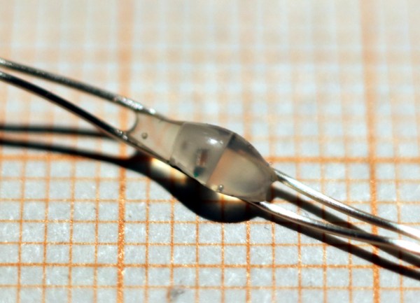
Although Christmas may be several weeks behind us, various colorful LED contraptions can nowadays be found in our houses at any time of year. [Tim] got his hands on an LED curtain that came with a remote control that allows the user to set not only the color of the LEDs as a whole but also to run simple animations. But these were not your standard WS2812B strips with data lines: all the LEDs were simply connected in parallel with just two wires, so how was this even possible?

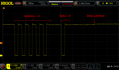
[Tim] hooked up his oscilloscope to the LED strings to find out how they worked, detailing the results in a comprehensive blog post. As it turns out, the controller briefly shorts the LED strip’s supply voltage to generate data bits, similar to the way old pulse-dialing phones worked. A tiny chip integrated into each LED picks up these pulses, but retains its internal state thanks to a capacitor that keeps the chip powered when the supply line goes low.
After reverse-engineering the protocol, [Tim] went on to implement a similar design using an ATMega328P as a controller and an ATtiny10 as the LED driver. With just a few lines of code and a 100 nF buffer capacitor across the ATtiny’s power pins, [Tim] was able to turn an LED on and off by sending pulses through the supply lines. Some work still needs to be done to fully implement a protocol as used in the LED strings, but as a proof-of-concept it shows that this kind of power-line communication is possible with standard components.
We’ve seen projects that send signals down a two-wire LED chain before, although as an add-on to a more ordinary LED strip. [Tim] is not the first to reverse-engineer poorly documented LED strip protocols, but probably won’t be the last either.


