This week’s How-To comes from our newest contributor: Logan Williams.
This simple guide will show you how to build a digital synthesizer that generates and manipulates square waves. Your synthesizer will have one oscillator, which produces a variable pitch controlled by a potentiometer, as well as an LFO which modulates that pitch at a variable frequency. The part count for this project is quite low, and it can be built for under $20.
Finding the Parts
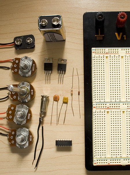
The first step in building this digital synthesizer is to procure the parts that you will need. Most of these can be bought at RadioShack, but RadioShack’s prices are often much more expensive than ordering online. All of the parts for this project can be purchased at Jameco, Digi-Key, or Mouser. We’ve provided Jameco part numbers below. If you don’t mind waiting, this is the best way to order parts.
| Item | Name | RadioShack | Jameco | ||
|---|---|---|---|---|---|
| 9V Battery Clip | 270-325 | $1.99 | 11280 | $0.30 | |
| 100K Linear Potentiometer | R2 | 271-092 | $2.99 | 255696 | $1.35 |
| 1M Linear Potentiometer | R3 | 271-211 | $2.99 | 255582 | $1.35 |
| 50K Linear Potentiometer | R4 | 271-1716 | $2.99 | 255549 | $1.35 |
| 10K Linear Potentiometer | R5 | 271-1715 | $2.99 | 255522 | $1.35 |
| 9V Battery | |||||
| IRF 510 MOSFET Transistor | Q1 | 276-2072 | $1.99 | 209234 | $0.69 |
| 3.5mm Audio Connector | 274-333 | $2.99 | 109496 | $0.53 | |
| 7805 5V Voltage Regulator | IC1 | 276-1770 | $1.59 | 51262 | $0.20 |
| 0.1 uF capacitor | C1 | 272-135 | $1.49 | 151118 | $0.20 |
| 1.0 uF capacitor | C2 | 272-1055 | $1.59 | 544956 | $0.20 |
| 40106 Hex Inverter | IC2 | Fairchild | $0.00 | 785071 | $0.47 |
| 47K Resistor | R1 | 271-1342 | $0.99 | 690540 | $1.00 |
| 1N4148 Diode | D1 | 276-1620 | $2.59 | 1537969 | $0.27 |
| Solderless breadboard | 276-002 | $14.99 | 20723 | $9.85 | |
Not Pictured
| Item | Name | RadioShack | Jameco | ||
|---|---|---|---|---|---|
| 22AWG Solid-core | 278-1221 | $5.99 | 36792 | $6.59 | |
| Amplified speakers | |||||
Tools
| Wire strippers |
Note: The potentiometers and audio jack must be either taped or soldered to 22 AWG solid core wire. Soldering is highly recommended, as it produces a more secure connection.
Creating an oscillator
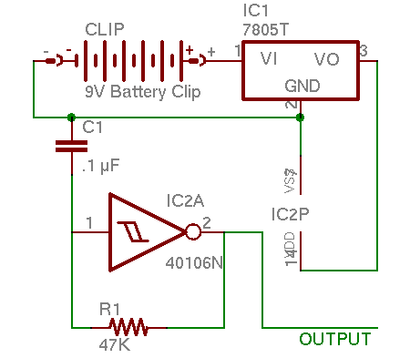
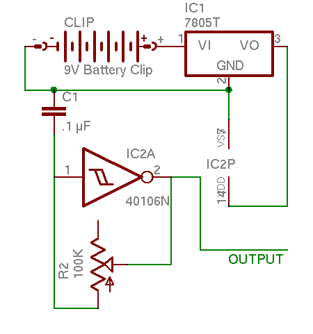
Before we can begin with the digital synthesizer, we must generate the correct voltage. Most of you will be familiar with using a 7805 5V voltage regulator. It is very simple; connect the +9V from the battery to the left hand pin, ground the middle pin, and the right hand is +5V.
The most basic circuit in any synthesizer is the oscillator. A square wave oscillator constantly alternates between two voltages, in this case +5V and 0V. We have a logic inverter to create this, which operates quite simply; if it is given +5V in (a logic 1), it give
s 0V out
(a logic 0) and if it is given a logic 0, it gives a logic 1 as output. When the input and output are connected together, it will oscillate rapidly between those two values: a 0 goes in, comes out as a 1, goes in, comes out as a 0, and so on.
The problem is that it oscillates much too fast. A resistor capacitor (RC) delay circuit can be added to slow it down. This forces the output current to charge the capacitor before it can pass through to the input. The resulting brief delay slows the oscillations to audible frequencies.
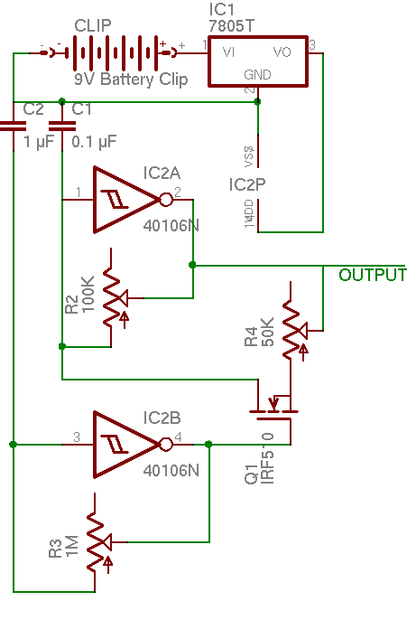
To build the oscillator, assemble the schematic below on a breadboard.
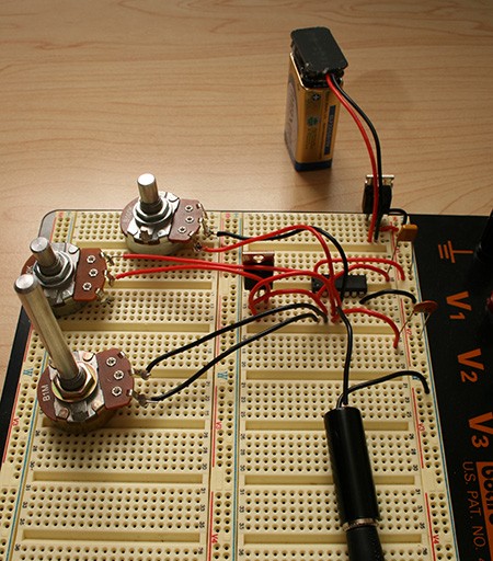
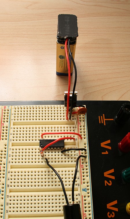
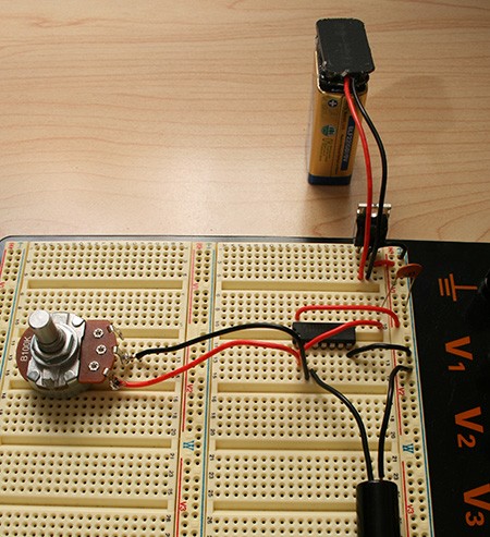
When done, the oscillator should look something like this:
Connect one side of the audio jack to 0V and the other side to the output, and it will sound like this:
Controlling the oscillator
We can make things more interesting by allowing the user to change the frequency. We replace the constant resistor R1 with a potentiometer, such as the 100K R2. This is a simple change to do, and is reflected in this altered schematic.
Now the oscillator sounds like this:
Much more interesting. Try playing an actual song, if you dare.
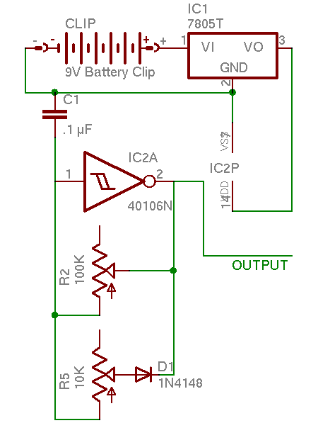
Duty cycle adjustment
We can add some basic timbre control to make the oscillator more interesting. The duty cycle of a square wave is how long it spends at logic 1 vs. at logic 0. For example, a wave that spends 1 ms at +5V and 1ms at 0V per cycle would have a 50% duty cycle. 1.5 ms at +5V and 0.5 ms at 0V would be a 75% duty cycle. To adjust the wave’s duty cycle, we can add another potentiometer and diode to the circuit. When the input is high and the output is low, current will be able to flow through both potentiometers, decreasing the amount of time it takes to charge the capacitor, and increasing the duty cycle.
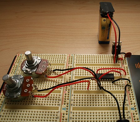
It should sound like this when completed:
Creating an LFO
A low-frequency oscillator (LFO) is an oscillator that oscillates very slowly, from 1 to 100 cycles per second. We will use an LFO to alternate the pitch of our oscillator between two different frequencies. This can be used for siren like sound effects, timbre control, or musical sequences.
The circuit to control the LFO is slightly more complex than the ones we have used before. Because it uses a capacitor with 10x the capacitance, and a potentiometer with 10x the resistance, the oscillations are 100x slower than our first oscillator. The LFO connects to the gate of the IRF 510 MOSFET transistor. When the output of the LFO is +5V, the transistor connects its source and drain pins. With these pins connected, current can flow through the second potentiometer, increasing the pitch. When the LFO returns to 0V, the potentiometer is disconnected, and the pitch drops back to its original level.
There are quite a number of sounds that can be produced with the LFO, such as this:
and this:
Conclusion
You have now made your own simple digital synthesizer. Keep experimenting with different control methods. The frequency is adjusted with just resistance, so almost anything can be used for an input. Try a photocell, or a flex sensor. Try combining the LFO and the duty cycle adjustment. Try using it to actually make music! We’d love to see what you come up with.


Excellent article, this is something I have always wanted to try but never had the time to figure out how to do it myself. Now I can finally get some hacks in!
Are we going to see follow up articles dealing with filters, etc?
the photo is in color? what’s going on here?
love to see more stuff like this, stuff I can actually put together!
This is great. I was showing a friend some basic electronics and had him hook a photocell to an oscillator. This is the obvious next step. I look forward to a howto on a microcontroller with a home built programmer.
tutorials? is this going to be a weekly recurring theme here on h.a.d.? I hope so! If so I’d vote for tutorial on building a digital thermostat, great project for dealing with micro controllers, LCD outputs relays, analog sensor inputs, as well as human interfaces and nice packaging.
This synth mod is quite cool, it’s simple enough too that I might already have all the parts I need to build one!
Interesting. Anyone have any idea how low this thing could create a stable wave at? I tried once to make a tone generator with a simple circuit using a 555 timer, but it wouldn’t go any lower than about 100Hz before it got really unstable. I ended up just using my computer’s soundcard with some tone generator software, which took me down to 1Hz without any problems.
The horrible sound samples remind me of a cigarbox in which I soldered a transistor noisemaker. With about the same irritation level. Early 80ies?
Twistedsymphony:
While that’s a great project for learning, its not a good one to do for use unless you’ve got a great budget and plenty of resources and time for testing. Here’s the reasons:
1. Measuring temperature. Is there a temperature rise in the thermostat? Is it constant? At what point do you measure the temperature and how fast does it react to an ambient change? All things you can deal with but count on many spins and a lot of ‘burn and learn’ code.
2. Failure mode. This is the big one. It would sure suck to come home and find your temperature set to 120. You can imagine a lot of possibilities here.
I know this because a few years ago I thought “I’m going to build a power stealing programmable communicating thermostat” and I did. After a TON of work, it worked almost acceptably, but I scrapped the project when I realized it could burn down my house.
Nice! with ducty cicle, we can do a PWM controls!
what a great tutorial! now for a diy resonant filter????
Definitely best noisemaker project I’ve seen (although I haven’t seen that many), and it really gave good explanations about how the stuff worked. Thanks!
This is cool, except square waves aren’t very nice to speakers. I’d like to see a synth that could do sine waves.
My other concern is to create real music with this, you’re going to need close to perfect pitch, or some sort of automated controller.
It’s been a while since I spent any time working on electronics, but would it be non-trivial to design an oscillator that doesn’t use an RC network to determine pitch? Mainly, I ask because I’d be interested in building a musical device which could generate at least an octave of accurate pitches.
Looks like an analog synthesizer to me, not a digital one.
True, they should change the title.
sweet, i might actually try this one.
This is great. Does anyone know a good place to get these parts in the UK?
OMG, Why isn’t the picture in black and white like all the others??? This is scary… Nice article…
Dirk:
It sounds like you need a simple microcontroller (pic, avr, msp430- pick your poison) connected to a keypad (or just a bunch of buttons), a transistor and a speaker.
The cool thing is that you could actually approximate a sine wave with an H bridge and pulse width modulation. Very few parts, easy to wire.
That would be a fun little project.
great how-to! I actually can build this one, and I love things to to with sound! I would love to see more like this!
analogue
@dave
so just program the uC to output such and such frequency with such and such button press? I figured that’d be the quickest route to take.
As for ‘approximating’ a sine wave with an h-bridge, after some quick reading it looks like that there’d be no ‘smoothing’ of the signal, so instead of just ‘slamming’ the cone (of the speaker) forward, it would also ‘slam’ it backwards. Wouldn’t that be more harmful than a straight square wave?
If I’m wrong, do let me know.
This is AWESOME! As many other people have said, alwasy wanted to do this, and glad to see some simpler hacks on the site for dumb people like me! :-)
You say ‘…the frequency is adjusted with just resistance, so almost anything can be used for an input…’ – does this mean I could use my guitar to somehow ‘trigger’ the thing?
Looks cool but there is no way that I could get this one work.
#17: Search for some Class D audio drivers. When designed properly, using PWM to drive a speaker is not going to break it.
it is an analog synth, just outputing a digital signal because it’s a square wave.
Re: pitch control, modular synth designers have been making voltage controlled oscilators for decades without microprocessors. Square, Saw, Sine, ring mods, VC filters, etc. There are tons of schematics on line if you are interested, and you can pick up a cheap midi->control voltage converter to hook up to your computer or midi keyboard.
Cool!
I did mine today, hopefully I had almost all the components.
But there is a problem: you should NEVER connect pin 2 to a speaker, you need to double invert it, otherwise the pitch will be different using other speaker (impedance changes)
I’m glad you guys enjoyed this project even if we can’t seem to figure out the proper name for it.
@gonzalo: yeah, I know. That is why I say that you should connect it to an amplified speaker, as then it will be buffered.
Great post! I would like to see more of these in the future. I still learning most of this stuff, and step wise articles with explanations of the parts and design are wonderful. Keep up the good work!
Ouch my ears. back to microcontrollers and stuff other than circuit-bending / crapiophile audio thanks!.
for anyone looking to extend this, synthedit (http://www.synthedit.com/) might be helpful for prototyping.
Well, no- speakers can only operate up to about 20kHz. Choose fets accordingly (fets that can run > 100kHz) and if you throw a higher duty cycle at 100kHz, its going to look to the speaker like a higher input voltage. If you REALLY want to make sure that 100Khz square isn’t buzzing the speaker at ultrasonic frequencies, you can put a RC filter on the way to smooth it out a little.
If you want to make a sine wave you just need to filter out all the odd harmonics. Easier said than done…but an inductor in series with the output should work.
Featured on Packet Storm on the main page.
packetstormsecurity.org
Really Cool!! As a suggestion for followups!
– how to modify the squarewave to become a sawtooth or sine
– how to modify the circuit to use a control voltage instead of a pot (I think I have examples of this circuit somewhere)
Hehehe. Cool project. We should have learn that at school.
Playing the two demos together is quiet funny too.
adding links to the music clips would be nice since I can’t for some reason load them through the flash applet
@dirk:
If you get a handful of momentary switches and resistors in parallel you can make the R-C network generate an octave of distinct pitches. You’d effectively be making a bunch of hard-coded resistances that are selectable instead of the linear sweep of the pot. It will be monophonic and you’ll probably have to do some work to tune it, but that’s the simplest way to do it IMHO.
Also, Dave’s H-bridge idea would work *with* pulse width modulation, like he said originally. Without PWM, you’re right, it would effectively just amplify the signal.
This is going to be fun, I hope to see some addons to this. Filtering would be great, other types of OSC sources, etc… Lets keep this one alive!!
Cheers.
How many of these could you power off of one 9v battery if you modified the circuit? I’m not very knowledgeable about electronics, but I’d like to have about twenty of the oscillators in one box, powered by a minimum number of batteries.
It would be even cooler if you could use rechargeable AAs.
dalasv: You should be able to run quite a few, twenty no problem. Each 40106 only uses about 20 ma, max, I think, and each 40106 provides 8 different oscillators. The 7805 can regulate up to 1A of current.
AAs? Sure, checkout Limor Fried’s mintyboost schematic: http://ladyada.net/make/mintyboost/ . It can generate 5V from 2xAA, and last longer then 1 9V battery as well.
the link to the radioshack 22AWG wire is incorrect, it links to their stranded 22awg wire. Here is the solid core wire:
http://www.radioshack.com/product/index.jsp?productId=2049742&cp
just so you don’t get the wrong type if you are buying it from there.
will: thanks, corrected.
Maybe just coincidence, but:
Tristram Cary:
created one of the first
electronic music studios
Dr Who
theme composer
dead at 82
April 28, 2008 02:03pm
Article from: AAP
TRISTRAM Cary,
the composer of
the Dr Who theme tune
and a pioneer of electronic music,
has died in Adelaide
aged 82.
Cary was also known for co-designing a synthesiser
used by rock artists including
Pink Floyd,
The Who and
Roxy Music
He co-designed the VCS3 synthesiser,
which became the must-have instrument
for such avant-garde classical composers and rock artists as
Brian Eno,
The Who,
Pink Floyd and
King Crimson..
He founded the
electronic music studio at
London’s Royal College of Music
in 1967
and,
seven years later
migrated to Australia
to establish a similar studio at
the University of Adelaide’s
Elder Conservatorium of Music.
The conservatorium’s head of music technology studies,
Stephen Whittington, said Cary’s contribution to music
was impossible to quantify.
“He laid the foundations,” Mr Whittington said today.
“Without him, we wouldn’t have techno, hip-hop or any kind of music
which is sustained by technology.”
Cary, whose father was prominent Irish-born novelist Joyce Cary,
came up with the idea of electronic and tape music
while a naval radar officer during World War II.
“He had a really unusual childhood, his father was an author and TS
Eliot
and James Joyce were always coming around for tea,” Mr Whittington
said.
“After the war, the Americans, British and Germans had a huge amount
of electronic gear which came onto the market and was incredibly
cheap,”
Mr Whittington said.
“That is when he began fiddling with things.”
Cary composed for Hollywood feature films, television, theatre
and concert music.
In 1991, he was awarded the Medal of the Order of Australia (OAM)
for services to Australian music.
He died last week at
the Royal Adelaide Hospital.
It was actually was written by Delia Derbyshire, but credit given to this guy because it was when women weren’t credited publicly by the BBC. Just saying.
flump:
Maplin are pretty good for electronic components. Although they may be a little on the pricey side.
Very interesting tutorial though. I might have everything needed to make one of these already.
So, what are the logistics for creating a sine wave? Is it possible to create a true sine wave using a different type of logic gate or something? I would imagine a slow-charge-slow-dump RC loop that might work, but I’m not so handy with the mental electronics planning.
@macgyver:
Not with a logic gate- the problem with gates is that they’re switching as fast as possible, giving as close to a square wave as the hardware will allow. For a given frequency, you can do it with a filter, but since this is an inherently differing frequency, that’s out too.
If you don’t mind analog circuitry, here’s a link to a quadrature oscillator which will give you a nice sine wave with a low parts count:
http://www.play-hookey.com/analog/sine_wave_generator.html
you do the same thing basically using a 555 timer. i did this for a digital logic class. notes are known frequences and can be found online. the 555 timer has i took 8 timers and using a formula and excel i used different resisters and capacitors and used push button switches to create a mini synth. the hardest part is troubleshooting when the notes arent correct.
i just built this and it’s awesome. sounds intergalactic. but i’d like to add a volume knob. any idea abt how that’s done? i put a 10k linear potentiometer in line with the output but that doesn’t seem to do anything.
@anyone trying to work out if this is analogue or digital synth. Just because the output can be represented as 1s and 0s does not make it digital. This is as Lo-Fi analogue as you get. I’d LOVE to see a similar project with a rudimentary VCO. If there isn’t one in 6 weeks when I get back from holidays I might work on it myself.
Hello. Great project!
Can’t get it to work though. No sound at all.
The voltage is transformed to 5V, so it works that far.
Should there be voltage between pin 1 and 2 of the 40106 inverter or is there a way that I can check so it works?