Brilliant Brick Prototyping

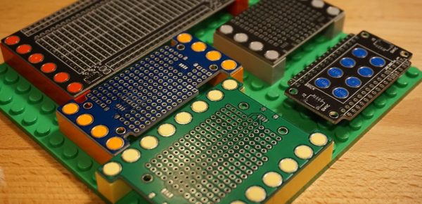
Have a rusty collection of protoboards wired together that would benefit from mechanical support? Working on putting together a robot and need to attach PCBAs without drilling holes, zipping a cable tie, or globing hot glue? Add some stud holes with [James Munns]’ Brick Mount! This isn’t the first time we’ve seen an interface between everyone’s favorite Nordic building system and circuitboards, but this implementation has the elegance we’ve come to expect from [James]’ software work.
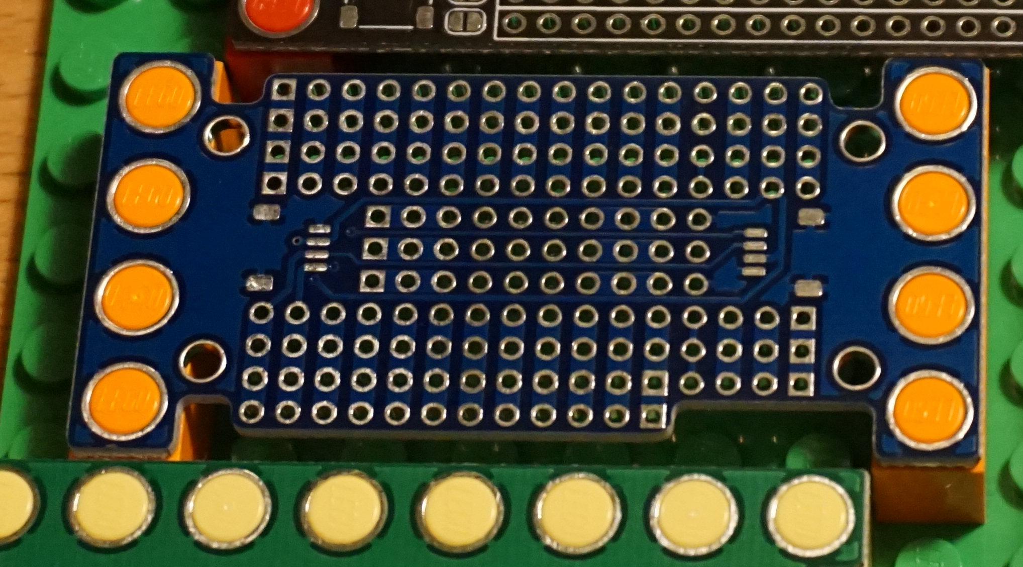
4×8 Feather Medium protoboard

The project repository contains two things: a KiCad library with components for holes in standard patterns and sizes (1×1, 1×2, etc) and a series of protoboards made with those hole components. The protoboards feature a couple common elements; QUIIC connectors for easy chaining between them and holes in the middle or edges for easy mounting on studs. Some are intended to be carriers for Feather-format PCBAs (very convenient!) and others are primarily undifferentiated prototyping space. Of particular note is the “medium” Feather breakout seen to the left, which incorporates clever cutouts to make it easy to wires down under the board so it can be mounted flush against another board.

The thesis here is that getting custom PCBs fabricated is easier and less expensive than ever before. So easy and inexpensive that fabricating customized protoboard to use in one-off projects is cost-efficient enough to be worthwhile. Waste concerns aside this does seem like a great way to level up those temporary projects which find a more permanent home.

LED Panel Lamp Is A Great Way To Use Protoboard

It’s now possible to source chip-on-board LED modules that have huge light output in a simple, easy to use package. However they can have major power requirements, and cheaper modules are also susceptible to dead spots.  [Heliox] put together a great LED lamp design the old-school way, showing there’s more than one way to get the job done.

Standard SMD LEDs are the order of the day here. The LEDs are laid out on protoboard in neat rows, making them easy to solder in place. This also makes power distribution a cinch, with the copper traces carrying the power to each row. Power is courtesy of 18650 lithium batteries installed in the back of the 3D printed housing. A GoPro-style mount is printed as part of the case, allowing the lamp to be easily mounted in a variety of ways.

It’s a quick, cheap and easy way to build a versatile LED lamp. With a diffuser installed and integrated USB charging, we could see this making an excellent portable device for on-the-go videographers or technicians. We’ve seen [Heliox]’s LED creations before, too. Video after the break.

Continue reading “LED Panel Lamp Is A Great Way To Use Protoboard”

Bottom Of The Barrel Connector: Tell Us Your Socket Hacks

Sometimes you get an epiphany for a project that will change the world. A simple device, on a custom circuit board with inexpensive parts that will disrupt the status quo and make you a billion dollars in no time. Then there are the times where you need to throw scraps of copper at a prototyping board and strangle nine-volts out by any means necessary.

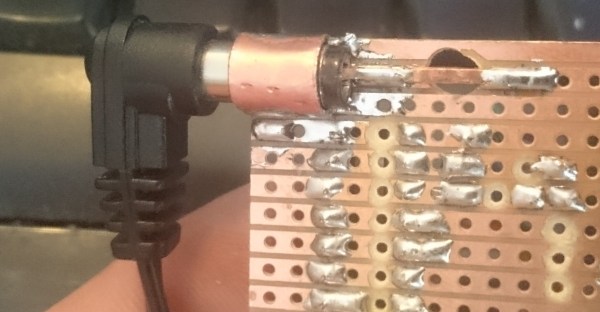
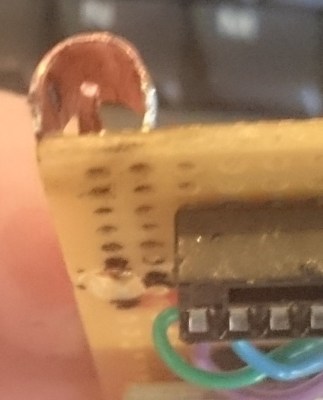
This is about the latter. In one of our Hack Chats, [Morning.Star] shared a couple of images wherein a barrel connector was needed, but there was no time to wait for one in the mail. Necessity birthed the most straightforward solution which did not involve shredding a power adapter’s plug. There is no link, [Stuart Longland] aka [Redhatter] screen-capped the image exchange and reminded us on the tip line.

Chances are you’ve faced this problem yourself. Everyone has a box of old wall warts somewhere, exhibiting a wide range of barrel connector sizes. If you can’t take the easy route of cutting off the connectors, what’s your go-to trick? Alligator clips are a horrid approach, and there aren’t really any clear winners that come to mind. [Morning.Star’s] hack is actually quite respectable! It appears to be a roll of copper (perhaps from tubing?) bent for a bit of spring tension on the outside of the barrel. The inside is contacted by thick copper wire with a kink to again provide spring action.

So, spill the beans. What’s your barrel connector trick and does it work reliably?

Evaluating The Unusual And Innovative Perf+ Protoboard

Back in 2015 [Ben Wang] attempted to re-invent the protoboard with the Perf+. Not long afterward, some improvements (more convenient hole size and better solder mask among others) yielded an updated version which I purchased. It’s an interesting concept and after making my first board with it here are my thoughts on what it does well, what it’s like to use, and what place it might have in a workshop.

Perf+ Overview

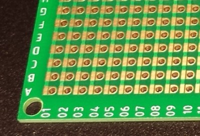
One side of a Perf+ 2 board. Each hole can selectively connect to bus next to it with a solder bridge. The bus strips are horizontal on the back side.
One side of a Perf+ board. Each hole can selectively connect to the bus next to it with a solder bridge. These bus strips are vertical. The ones on the back are horizontal.

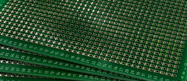
The Perf+ is two-sided perfboard with a twist. In the image to the left, each column of individual holes has a bus running alongside. Each hole can selectively connect to its adjacent bus via a solder bridge. These bus traces are independent of each other and run vertically on the side shown, and horizontally on the back.

Each individual hole is therefore isolated by default but can be connected to one, both, or neither of the bus traces on either side of the board. Since these traces run vertically on one side and horizontally on the other, any hole on the board can be connected to any other hole on the board with as few as two solder bridges and without a single jumper wire.

It’s an innovative idea, but is it a reasonable replacement for perfboard or busboard? I found out by using it to assemble a simple prototype.

Continue reading “Evaluating The Unusual And Innovative Perf+ Protoboard”

Philips Lamp Upgrade

Increasing The Brightness Of A Philips LivingColors Lamp

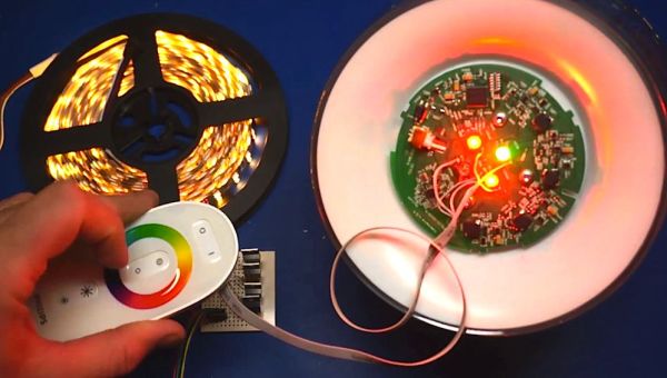
[Martin] recently purchased a Philips LivingColors lamp. It’s a commercial product that basically acts as mood lighting with the ability to change to many different colors. [Martin] was disappointed with the brightness of his off-the-shelf lamp. Rather than spend a few hundred dollars to purchase more lamps, he decided to modify the one he already had.

[Martin] started by removing the front cover of his lamp. He found that there were four bright LEDs inside. Two red, one green, and one blue. [Martin] soldered one wire to the driver of each LED. These wires then connected to four different N-channel MOSFET transistors on a piece of protoboard.

After hooking up his RIGOL oscilloscope, [Martin] was able to see that each LED was driven with a pulse width modulated signal. All he had to do was connect a simple non-addressable RGB LED strip and a power source to his new driver board. Now the lamp can control the LED strip along with the internal LEDs. This greatly extends the brightness of the lamp with minimal modifications to the commercial product. Be sure to check out the video below for a complete walk through. Continue reading “Increasing The Brightness Of A Philips LivingColors Lamp”

Solder Trick To Make Your Own Surface Mount Breakout Boards

surface-mount-breakout-trick

We think you’re really going to enjoy this trick for making surface mount breakout boards. It’s common to use magnet wire to connect individual pins of a surface mount part to breadboard friendly protoboard with pin headers. What’s new here (at least to us) is that [Raul] solders one wire to both pins directly across from one another.

The image at the left shows an eight pin part with four wires soldered in place. To get to this point he first taped the wires down to a work surface being careful to space them to match the pitch on the chip’s leads. He then tapes the chip in place and solders all of the legs to the wires. This seems to kill two birds with one stone as aligning one wire to one leg is tough. From there he flips the chip over and cuts the wire spanning under it. This leaves an easy job of soldering the trailing side of the wire to a hunk of protoboard.

It’s perfect for chips with a small number of pins. Of course you may still want an etched breakout board for something with a ton of leads.

Switch Mode Breadboard Supply From A PTH08080

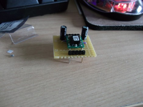
[Ben] wanted a switch mode power supply for his breadboard. He ordered a PTH08080 module which is made by Texas Instruments. The spec sheet would make it a great choice for him, but he was not happy to learn that the pinout doesn’t conform to the 0.1″ spacing used by solderless breadboards. His solution was to make a breakout adapter from some protoboard.

The PTH08080 can source up to 2.25A. It accepts 4.5-18V input and can output 0.9-5.5V. The best part is the efficiency that a switch mode supply achieves compared to linear regulators. This design adds in two capacitors which are suggested in the application circuit from the datasheet (PDF). Notice that there are two headers on the breakout board. One supplies power and ground to the breadboard. The other gives him a place to connect the adjustment resistor used to select the output voltage. This connects between one pin on the PTH08080 and GND. [Ben] plans to upgrade the design by included a precision trimpot for easy output voltage adjustments.