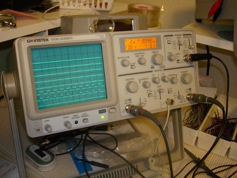
[Mike Bradley] wanted to use his oscilloscope to display 8 channels of digital signals. Alas, the analog unit didn’t have this capability. Not to worry, he threw together an adapter module that does the trick. Using a PIC 18F26K20 microcontroller he inputs four or eight channel digital logic (at 5V) and filters the output to an analog signal that the oscilloscope can interpret. What you see in the photo above is the result.
Use An Analog Oscilloscope To Display Digital Logic


This woulda been good to have yesterday.. ;)
His workbench is too clean!
looks like something I would find very useful
Now this looks like something I could really use! I shall make note of it…
@medix
agreed. far too clean.
A little off topic, but as a hobbiest I have been looking at buying an oscilloscope. The only one I have ever used was a Agilent in lab when I was getting my BS. What would you guys suggest getting or specs to look for?
I don’t quite understand, what kind of mode allows the scope to show 8 horiz lines? Or is the adapter switching them so fast that it only looks like it does that?
agilent/tektronix/lecroy are all good.
rigol are cheap n cheerful
lots of good used scopes on ebay.
That is a cool idea, I haven’t had a chance to look at the code but I am guessing by alt mode he means that is he drawing each trace one at a time, and cycling through which trace is being drawn.
There are 2 things I still don’t quite get though, mainly
1. How does it choose the timebase? It looks like assumes a moderate timebase (presumably chosen to give a non flickering trace on the scope), and you can ‘zoom in’ further if you need to by adjusting the scopes time base.
2. How does it deal with synchronizing the trigger? It seems like if this is to be used for a logic analyzer of sorts this would be a big issue, and as it is it doesn’t seem like it does much to synchronize the traces in absolute time (not just starting at a random clock bit for each trace) unless it is storing a capture, then displaying it.
Sadly since I have a digital scope this would be somewhat tricky to use, since you can’t trick the CRT into working like an analog does.
This used to be a fairly common hack/project in the electronics mags, B.I. (Before Internet). I have a couple old mags in storage with some pretty hairy analog projects, like a 3-input ntsc video switcher with framebuffer, sync, and wipe effects. God, I’m glad those days are pretty much over. Doing information/signal processing using analog circuits was a PITA (Pain In The *ss).
@awelker:
Check out the GW Instek scopes like the one shown in the picture. Prices start at $350 and I am quite happy with mine.
Very clever.
@rallen71366 – yes, I recall seeing several similar projects in Poptronics et al back in the day. Though the result was the same, I’m guessing modern ucontrollers make this much easier to implement (as opposed to a crazy analog front end).
Regarding decent scopes, I guess a bit depends on what applications you desire, but personally I think a decent old Tek or HP on eBay would be a better value than any new ‘cheap’ scope…
In the ol’ days, real men did that with shift registers and common logic gates. At that time there were no microcontrollers, so it wasn’t a matter of choice.
Doing it the old way is IMO an interesting exercise I would recommend to schools to teach students digital electronics with an actual useful project.
For example, you can AND each digital input with the output of a shift register, then use each AND output to drive a voltage divider that will bring up or down the relevant track. The scope trigger can be left free running, but synced to the shift reg reset, so you can also monitor signals wrt time.
Oh my… This, I’ve got to bookmark. Nice find Mike. Very nice find.
This could def. come in handy, thx for posting!
Seems to require an expensive for-pay C compiler to build the project. Lame.
Hmm how would you got one of these oscilloscopes?
@achra
Microchip and PICs are annoying like that; AVRs thankfully have open source support (AVR-gcc, WinAVR, etc.)
Don’t fret though, they have trial versions:
http://www.microchip.com/stellent/idcplg?IdcService=SS_GET_PAGE&nodeId=1406&dDocName=en010014
achra: I’m sure you could ask him to upload a pre-compiled hex.
Or take the time to re-write the peripheral setup routines.
Or use the 30 day free demo.
Sadly, the free demo doesn’t support the PIC he is using.. I think I will rewrite it for a free compiler.
It seems like he is just using a sort of chopped mode, where he sets the DAC to the level of one of the channels plus the offset for that channel, and leaves it there for a little while to get a visible trace on the scope. If you cycle through the channels fast enough, you can’t see the interruptions in the lines.
Becauses he uses the external circuit for the trigger signal, i’m guessing he can’t freeze the image unless the signal is repeating.
Personally, i think i’d store the captured data, have the PIC generate the trigger signal for the scope, and use both channels to draw 4 signals each. As it appears he can draw 8 digital channels with a single channel on the scope, the second channel could be used for something else.
When you store the signals, it would be fairly easy to send them to a PC and use some tool (possible just Excel / Oo Calc) to draw the waveforms for use in documentation.
@awelker
The Rigol DS1052E, you won’t find a better one for less. See the EEV blog teardown (he has a couple of reviews also)
http://www.eevblog.com/2009/10/12/eevblog-37-rigol-ds1052e-oscilloscope-teardown/
Also, if you check out the comments and his forum, you’ll find that there are several people trying to figure out how to mod it to be a 100 MHz scope rather than 50 MHz. It has seemingly identical hardware, with some work I bet a filter can be found on the analog frontend that limits the bandwidth. Additionally, there is a logic analyzer version that costs something like $1k, rather than $400 on dealextreme.com for this one. It looks very very similar.. if you open up the DS1052E there is a header for the logic analyzer going to a PLL. There’s a button that enables it which doesn’t appear on the outside, but has been cut out of the rubber button set on the inside. If pressed, it says “feature not installed” but the firmware seems to be the same. Lots of hacking potential, and a good scope with a 3 year warranty otherwise.
Anyone have details about the Poptronics projects mentioned in this thread?
id build one if i had an o-scope. Donations anyone?
I wonder, when using a controller anyway, wouldn’t it be easier to hook it up to a PC via the serial interface.
Of course you couldn’t transfer data in real time at a decent speed. But you could capture a set of data to the internal RAM and then use the PC to display it.
Ok, I got a response from the author, he says that he is more than happy to post a programmable hex when he gets back into town. Thanks Mike!
@awelker, @shbazjinkens
I second shbazjinkens’ DS1052E recommendation. However, any scope that you get from China will not come with anything other than a China warranty, so you’ll have to send it to Beijing if you ever have a claim. It will also come with a China power cord, but it’s the same as a desktop PC power supply’s cord (unless they added some special shielding sauce to the factory one).
I know of this first-hand. For ~$100 off you don’t get local warranty service. Just so you know.
Check eBay for some good used scopes. I bought a used Fluke 99 Scopemeter Series II for $150. It’s portable!
Thanks for all the geat comments guys, I apreciate it.
To clarify a few things.
I am using a DAC, that basicaly generates a staircase waveform, however, the height of each step is dependant on the logic level.
Also, this only uses 1 analog input channel on the scope to show 4 or 8, he 2nd channel is free to use. 4 or 8 is available to allow for higher speed.
This is a real time display, no capture, as for timebase, you set that on your scope like normal. just trigger off the external triger input, and adjust timebase accordingly
I am out of town right now (stuck in hotel room) but I will post the .hex file online for all to use when I return monday (2/15/10)
Also, I like the idea of a capture, perhaps I will play with that idea, but I realy needed real time when I built it, I was working on a project and I needed to see the relation of PWM signals in real time.
Again, thanks everyone.
@awelker – I second shbazjinkens’s DS1052E recommendation.
Be aware that if you don’t get your Rigol product through an official distributor (and I doubt that DealExtreme is one), then you don’t get “local” warranty service, and you have to send it back to Beijing if you have a warranty claim. That’s the tradeoff you have to make if you go around your official, local distributor channel. FYI.
The hex file has been uploaded to http://www.mculabs.com for anyone wishing to try and not compile.