A while back we saw a logic clock that used the alternating current frequency from the power grid to keep time. We asked for information on your projects that use this method and we got a lot of comments and tips. Today we’re sharing [Doug Jackson’s] method which he used in his word clock.
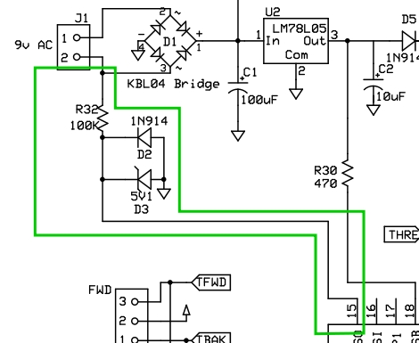
The schematic above is from that project and we’ve outlined the important part in green. [Doug] pulls a signal from the 9V AC power before it hits the bridge rectifier, using a 100K resistor and a zener diode to protect the microcontroller pin. The code for that project comes as a hex file but he sent us the C code pertaining to this timing circuit. It’s written for PIC but you’ll have no trouble adapting it to other microcontroller families. Take a look after the break.
//  Set the frequency of the local mains - MUST BE SET OR THE CLOCK WILL BE USELESS

//#define MAINS_FREQ 50      // the local mains supply frequency for Australia
#define MAINS_FREQ 60    // the local mains supply frequency for the USA

T1CON   =   0b00000011;   // Timer 1 control
//    Prescale - 00 - 1:1,   Oscilator disabled,  External Clock,  Timer Enebled

void incrementtime(void){
// increment the time counters keeping care to rollover as required
 sec=0;
 if (++min >= 60) {
       min=0;
       if (++hour == 13) {
            hour=1;            }
     }
}
                                    void interrupt my_isr(void){
      // test to see if it was a Timer 1 interrupt - External mains source
      if ((TMR1IE) && (TMR1IF) && (mode==0)){
           sec++; // increment the seconds counter
          TMR1IF=0;
          TMR1H=0xff;
          TMR1L=MAINS_DLY;    // reset TMR1H and TMR1L to go off in the
                              // appropriate number of cycles based on the local
                              // supply frequency
          }

}

void main(void)
{
  init();  // initialise the hardware
  testleds(); // test the LED array
  version();  // Display the version number of the software

  displaytime(); // display the current time

  TMR1H=0xff;
  TMR1L=MAINS_DLY;    // reset TMR1H and TMR1L to go off in the number of
                      // mains cycles based on the local mains frequency
    ei();
  while (1) {
            //test to see if we need to increment the time counters
          if (sec==60)
          {
              incrementtime();
              displaytime();
          }

          ....... etc etc etc - do the display of the time as required.....
   }
}


It may be irrelevant, but I just noticed a funny typo in that script. It was a comment, though, so nbd. See if you can find it and guess why it’s funny.
Is it that hard to buy an oscillator off Digikey? Using AC as a timing signal is a fairly standard student exercise, but it’s problematic in actual practice.
Atmel suggests using only two resistors for AC mains interface since protective diodes are already in place inside AVR.
See http://www.atmel.com/dyn/resources/prod_documents/doc2508.pdf
The same advice applies to the PIC. In fact, you can also run 120VAC into the IO pin so long add you use a sufficiently large current limiting resistor.
Why put D3 in parallel with D2?
It would be much useful right before R32 as a half rectifier.
@fluidic: I used a 10Mhz clock on my last clock project as an “excercise”. That was problematic. His 1:1 prescale looks sensible to me. The concept of time is just weird.
Nice work. Lots of documentation on hw and sw. Nice instructable.
@fluidic
There are instances where using a oscillator isn’t appropriate, in terms of cheating and saving components it isn’t really valid but if you want your controller to be sync’ed to the AC signal you need to use this method. An example would be lighting dimmers that need to trigger SCR’s relative to zero crossings.
As clock, not so good – I’ve got a couple of cheap digital clocks that already run slow or fast when the power goes out and the generator is slightly off on its frequency. I’m measured household current and it’s never exactly 60hz –close, but not exact.
ON the other hand — I wonder if this would be a useful signal to use in some kind of noise canceling circuit for high end audio equipment. Maybe using the power cycle frequency itself as a canceling wave against the ever present 60hz hum.
i use
transformer>opamp>1/60divider
oh and a 4th wave rectifier
One of the other handy things to use a zero crossing detector for is when building digital dimmers.
We designed & built a system in college that was 100% digital and comparable to the bleeding edge of theater lighting of it’s day. Basically, you start a preloaded countdown timer on that zero crossing. When the timer hits 0, turn on a solid state relay. The SSR resets itself at the next zero crossing. Reload the counter, start again.
The hard part comes in doing the math needed to do 192 channels of dimmer crossfade in real time.
In 1981 we built the whole thing in discrete wire wrapped ttl. Now I’d just use a PIC or the like on every channel.
I’ve been waiting for this to come up. My clock runs off of a switching power supply so I’m planning on using an opto-isolator hooked up to 110VAC but I’m not yet sure what else is needed, probably a diode rated for at least 200v and a resistor with a large amount of resistance? Like a 100K?
@Andrew: Power utilities in the U.S. intentionally manipulate the AC line frequency from time to time to keep line-locked clocks reasonably accurate. The exact standard depends on what grid you’re on, but the worst of them try to keep the accumulated error to within +/-10 seconds. In other words, short-term the frequency drifts significantly but the long-term accuracy isn’t bad. Obviously if your power goes out, though, all bets are off; a home generator is probably lucky to stay within +/- 10% of the correct frequency.
One useful point is the circuit as shown will probably only work reliably if the IC being driven has Schottky inputs. Otherwise you’ll probably want some kind of signal conditioning to make the rise time faster.
My Uncle owns an old Binary clock sold many many years ago. It relies on AC frequency for keeping it’s time. Amusingly, he got one for my other Uncle who lived in Germany at the time. Because of the frequency difference, their clock kept on getting off :)
@Orv what sort of scale with long term accuracy?
I’ve had issues with time accuracy over a term of a few months with some plug in clocks. I’m educating myself in the direction of monitoring AC timing with my NTP synced clock.
Anyone know if the cheapo battery backed clocks are clocked by AC while not running off of battery?
I used to service master time clocks as part of my job. We did a lot of work in schools. We had one school who’s master time clock would always be noticeably slow after maybe 2 weeks, and on a regular basis. We replaced the unit several times and bench tested the removed unit but could never duplicate the problem. After talking with tech support, it turned out that the MTC was set to sync to the AC power by default, and not the internal crystal. And this particular school had AC that wasn’t quite 60hz.
Where does the 9v AC come from a 120v -> 9v step down transformer??
Grid freq shifts during the day. Avg cycle for 24 hrs must be 60 hz in the US. It’s slower in daylight(peak) hours and purposely sped up at night to recover for the clocks that use grid freq for time keeping.
Is this true or urban legend?
It makes sense that frequency might end up > 60Hz overnight due to lower load, rather than an actual intentional thing to “catch up”.
Who keeps count / keeps track of how much frequency moves ahead or behind?
The 1N914 diode in parallel with the zenner is redundant. As you should know, the zenner acts like a normal diode when biased directly. You bias it in reverse for the zenner effect.
Even so, both diodes are redundant as the mircos contain protective diodes.
You need to put some filtering on the AC input, otherwise interference pulses occurring just as the cycle passes through zero will cause the clock to run fast. From personal experience.
When I was a kid (the 60s/70s) the city had it’s own dam and power system – it wasn’t connected up to the national grid – but at the power station there were two clocks on the wall – one connected to the national grid, the other to the local one – some time after midnight they’d speed up the generators or slow them down a little bit to make the clocks right (and all the clocks in town)
Oh and soldering to a QFN is really hard (hair tearingly frustratingly annoyingly hard), but not impossible – I’ve found it’s easier for prototypes if you make the pads a little larger all around when you lay it out so that there’s some metal to get the iron down on to transfer some heat in to the joint
@Kyle: I just started using a Maxim DS3231 in a work project. The two features that made me choose it are it has an internal crystal so it starts & stays accurate (±2 Minutes per Year) and it just needs a watch battery to stay backed up for 8 years.
My project is still in breadboard stage but it’s kept good time for 2 months for me now (while I still build/rework other section of the project).
Its a little pricey ($7.50@1@DK) but I can live with that. I need it for time stamping data logging without the operator having to set the time/date each time the unit is run.
Most off the shelf digital alarm clocks use the frequency of mains for timekeeping, and at one time computers often did too.
And it really works with damn good precision since my digital alarm clock never needs adjusting whereas my expensive computer needs adjusting on a regular basis, makes yo wonder why they didn’t specify the computer PSU’s to output a clock signal, would cost next to nothing too.
in some countries, AC frequency is used with a voluntarily injected drift to drive billing particularities like a tarification change during some periods, like a -25% of charge after 23h, until 4AM, in example.
So, be careful if you’re going from 50 to 60hz, you could have surprises.
the frequency is in the KHz range and is only a few volts, but during Peak overloads the generators will sometimes shift the output frequency a few Hz to make the transformers just that little bit more efficient. Doesn’t happen often, usually under dire circumstances.
@papa I used to have a meter that switched between night rates and day rates, didn’t influence clocks at all.
around here when we had it it was just a billing thing, they cant switch phases on you anyway, there is a ton more items dependent on mains timing than just clocks (um tv comes to mind)
cool :-)
they changed the frequency in poland, their is a layer of TVs in all the landfills.