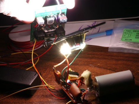
Since we’re not high-end camera aficionados it was a surprise to us that the hot shoe that allows a camera to interface with a flash module has changed rather dramatically over the years. Apparently the interface used to be mchanical-electrical in that the camera would use mechanical means to connect two electrodes from the hot shoe. It didn’t matter the voltages it was switching because the camera didn’t have an electrical system connected to the interface. The problem is that connecting a modern camera to what [David Cook] calls ‘legacy’ flash hardware could damage it. So he developed the Safe-Sync to interface modern cameras with older flash modules.
You can see the board which he’s holding up in the image. It includes a lot of nice features, like the ability to be powered from the external flash, or from a battery. There’s also an optional momentary push switch which can be used to test the flash control (or hack it for other purposes). In addition to providing protection with older equipment, this could also be used to interface flash modules from different manufacturers with your camera.


“In addition to providing protection with older equipment, this could also be used to interface flash modules from different manufacturers with your camera”
Uhh really?! Modern flash modules communicate via a serial bus with the camera receiving all kind of data like exposure settings, the focal distance, etc. There is iTTL (Nikon) and eTTL (Canon) and a couple of others and many outdated one and they all speak a different “language”. This you can’t fix with some analogue circuitry.
However, it would be an awesome Safe-Sync2 feature.
Next step I see is a nice PCB based on SMD just sitting between the flash and the camera.
although the TTL may not be cross-brand compatible, this should still let you use them in manual mode (as many strobist photogs do)
there is a hotshoe version, but the price tag is part of why we DIY:
http://www.bhphotovideo.com/c/product/245292-REG/Wein_W990560_Safe_Sync_Hot_Shoe_to.html
True manual mode would work.
Nevertheless, a e-TTL to i-TTL, etc. converter would be awesome ;)
Well the DIY version is nice but wouldn’t it be possible to make a SMD version and get this sold e.g. via SEEED studio or Sparkfun?
Wow. Where was this 10 years ago when I killed my Rebel EOS with a ‘legacy’ flash… As much as I hate all the proprietary connectors for gadgets (USB A, B, mini, micro, x,y,z,…), this was a non-trivial protocol change that should have warranted a different hot shoe (and maybe a convertor / adapter to enable legacy flash units)
There have been a few projects like this but none really caught my eye..
Great job on the overlays to explain the current flow!
I don’t see any mention of wattage for the components?
I recently dug a couple of old “potato masher” Sunpak’s out of storage and have been very excited about using them but stopped when I discovered I couldn’t just plug them in.
Well it seems the camera business is kind of much different compared to electronic. You see all the time changes which forces you to buy new camera equipment. However, these changes are not as obviously and often only made on business purpose. E.g. certain lens do not 100% work with entry-level cameras. They fit mechanically and would work but the firmware denies to use them. Flash changes the protocols but not the plugs, Other plugs change but the electric function remain the same… etc.
Now days, the flash has the TRIAC built in, or uses some other means to fire. Connecting the two trigger wires together (all you need in manual mode) sends the signal to the flash that it should fire now. Old flashes just used the mechanical switch in the camera to complete the circuit, and dumped all the current at 250v to 600v through the hotshoe, camera, switch, and back to the bulb.
First thing I bought for my new digital was a safe-sync shoe connector. Minolta made a smart move, and changed the type of shoe they used when the cameras went from mechanical to digital communication, but while they used measured voltages for the serial communication lines, the flash trigger lines were still ‘trigger 1’ and ‘trigger 2’ and were still a mechanical switch. So, in the Minolta/Sony alpha world, you have old ISO hot shoe flashes, middle ground Minolta flashes with limited voltage on the communication lines but less care about the trigger lines, and late model Minolta digital safe and Sony that have something like a 5v limit on the trigger lines.
Myself, I’d be interested in (and have on the drawing board) a multiple strobe connector that is safe to 600 volts or more, with each head isolated from the rest. Mostly because I’ve tried to connect a few old surplus flashes to PC-sync cables and had them constantly trigger each other. Seems that even when the same company made the flashes, there was no agreement on whether the outer ring of the PC cord was – or + volt.
All this reminds me why I like wireless trigger systems again.
…All of this can be avoided with a $20 el-cheepo wireless trigger system from china. I mean, nifty project, but doing all this work to trigger a flash on camera? On camera flash is bloody horrible anyway.
I have one of the wireless chinese systems. Somewhat unreliable.
I’ve seen versions of this that consist of nothing more than an optocoupler, a triac, and a resistor or two. When carefully planned they can be built into an old flash and no one would be the wiser.
There’s actually a ton of info out there (from people who are into manual flash photography) about which flashes are safe, how to measure flash trigger voltage, etc.