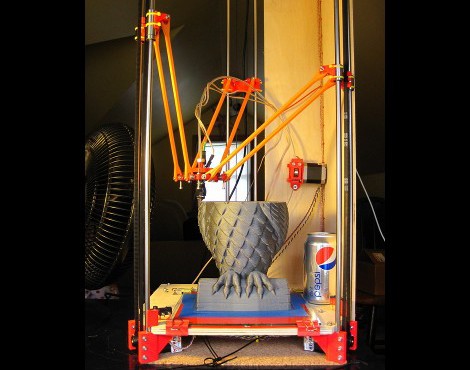
This 3d printing delta robot really seems to solve a lot of the hurdles faced by previous offerings. With other delta printers we’ve looked at the motor control of the three arms is usually a it complicated. On this build the motors can just be seen in this image at each corner under the build platform. Each motor has a belt that loops from the bottom to the top for the machine, driving an arm along two precision rods.
It’s also interesting to note that the printer head doesn’t have a motor mounted on it for feeding the filament. Instead, the motor is mounted remotely. You can see it above the soda can in this image. It feeds the filament through a hollow tube spanning the gap between the extruder and the motor. This acts as a Bowden cable. With less mass to move this may make it easier to control the location of the print head.
After the break you can catch a clip of the team showing off the speed and dexterity of the delta bot, followed by a printing demo.
[Thanks Kyle]


I want this!
lol
For nearly a year I’ve wondered if this type of setup would work. I’ve lacked the drive to get myself moving to test the idea and now I don’t have to! Hooray for other people!
This message brought to you by procrastinators of America.
Very well done guys, I love the build. :)
this one is sexy and fun to watch. needs to sell it as a kit, this one would be fun to put together.
This is absolutely brilliant! a clean, precise implementation.
A couple of observations: characteristically, Z axis motion (up and down), is impacted by gravity. Things come down more readily than they go up! While an elevator-style counterweight could be implemented, this would increase inertia. You could implement a vacuum assist counterbalance (Airpel), but given the lengths of travel… well, perhaps its best to keep the main carriage light!
I always thought delta format robots were tied up in patents but I have no idea how this affects the Maker community. Perhaps at this point they are all expired!
I thought I had come across a quad linkage system once (maybe here) which would make the math a good bit more simplistic. I think it also was done to avoid patent issues, but I could be very wrong.
I think this implementation is fantastic and my hat is off to these folks!
Z axis rapid speed asymmetry is only an issue if you *really* need to maximize rapid speeds. If not, just determine the limit on upward acceleration and speed and use that for both directions.
Most 3D printers don’t need much Z speed though, so usually there is no need to counter-balance the weight. Anyway, it serves to eliminate backlash in Z, so as long as it isn’t an impediment, you can consider it a feature.
The math is actually trivial. I thought it was hard at first, so I worked it out.
All of this is in two dimensions:
First define three vectors from the origin to each support/drive pillar: A,B,C
Define a vector from the origin to the desired location of the print head: W
Define the length of an arm: r
Define the height of each carriage on its pillar: ha, hb, hc
Then the horizontal distance from each pillar to the print head is:
a = |W-A|
b = |W-B|
c = |W-C|
Then, knowing the length of the arm, each height is defined as:
ha = z + sqrt(r^2 – a^2) = z + sqrt(r^2 – (W-A)^2)
hb = z + sqrt(r^2 – b^2) = z + sqrt(r^2 – (W-B)^2)
hc = z + sqrt(r^2 – c^2) = z + sqrt(r^2 – (W-C)^2)
This is actually pretty easy math!
I could only follow you until you said “three vectors”. Am I birdbrained?
Inyaner….
to explain the origin of the math…
Its important to note that a delta robot is capable of roll and pitch movements that arent necessary in a layerwise build. To use those movements you would need a more complicated trigonometric formula.
However, this formula assumes all right triangles which will keep the head perpendicular to the build plane……very simple.
Its all Pythagorean theorem.
a²+b²=c²
The distance from the z axis to the extruder tip is the base (b) of 3 right triangles…this distance is unique to each of the 3 arms.
The length of each arm is the hypotenuse (c)…so this is the same for each arm.
Using this his formula computes the height of each triangle for the intended head position.
Thanks Annirak…before your posting I hadnt even considered such a simplified equation for perpendicular delta travel….Ive always just stuck with the more dynamic trig solution.
I just wanna say that the quality of comments on this site has really improved over the last year.
@techartisan: No problem! I tried to do it with dynamic trig at first too!
While you’re right that *some* deltabots are capable of pitch and roll, a 3-actuator delta bot can only position in x,y,z. The problem is this: any object, unconstrained, has 6 degrees of freedom: x,y,z, yaw, pitch, roll. In fact, it seems that you need one arm per degree of freedom. There might be one you can get for free, but I’m not sure about that: I know that 4 arms is unstable, but I’m not sure if 5 arms is or not.
Since we want to use the smallest possible number of actuators, we know that we need to constrain yaw, pitch, and roll. Rostock does this by tying pairs of arms together and attaching them to the same actuator, creating parallelograms which constrain the yaw, pitch, and roll.
@Techartisan I had a few more thoughts on this problem.
Suppose you have a 6-independent arm deltabot, with arm-mount carriages that move only in the z-axis, like Rostock (the math is very similar for sliding-arm deltabots like this one: http://www.youtube.com/watch?feature=fvwrel&NR=1&v=NDzUiZsbQtw )
1. Find the platform connection points of the arms on the toolhead:
define six vectors (p1..p6) which point from the centre of the toolhead to each attachment point.
2. Orient the toolhead. All of the vectors (p1..p6) exist in the horizontal plane, with unit normal vector n0 = . To angle the toolhead correctly, you just need to orient the normal vector and apply the same transform to each of p1..p6. This is two matrix rotations M1 (angle X around the x-axis) and M2 (angle Y around the y-axis). Once calculated, they can be stored as M = dot(M1,M2).
M1 =
[ 1 0 0 ]
[ 0 cos(X) -sin(X) ]
[ 0 sin(X) cos(X) ]
M2 =
[ cos(Y) 0 sin(Y) ]
[ 0 1 0 ]
[ -sin(Y) 0 cos(Y) ]
Now, multiply each p1..p6 by the combined rotation matrix M to get the new endpoints q1..q6
All the trig is now over. The rest of this solution uses plain vector math.
3. Position the toolhead. Use a position W = . Each new endpoint, q1..q6, is positioned using W to obtain e1..e6:
e1 = W+q1 = M*p1 + W
e2 = W+q2 = M*p2 + W
etc…
4. Find the heights of each carriage. From here, it’s essentially the same problem as before. Assume arms of length r, and pillars in positions P1..P6, where each Pn has x component Pnx and y component Pny. We know the x/y part of each e vector, so we can construct a set of right-triangles. The height of each carriage (h1..h6) is calculated as follows:
h1 = z + sqrt(r^2 – (e1x-P1x)^2 – (e1y-P1y)^2)
h2 = z + sqrt(r^2 – (e2x-P2x)^2 – (e2y-P2y)^2)
etc…
This style of math will work for any linear-actuator based delta bot. It’s a little more complex with the rotating-arm delta bots.
@oddjobzombie
+1
..on the comments
When looking at a “professional” delta bot, the design usually varies a bit. To make roll and pitch possible the arms are connected to the platform by a balljoint. The arm angles now also need to be controlled to achieve full control again. Yaw is hard to achieve from just the arms. Adding a rotating table to the object table would be much easier to do.
Delta bots are patented up to the hilt. This is not a problem for a maker if he makes designs for his own use. The real problem with patents only starts once you try to actually commercialize the product. (Aka, sell blueprints or complete bots)
In fact I’m sure there is a nice proof for your one-arm-per-DOF theory (probably involving euler’s polyhedron formula)…
Interesting robot, that said it’s not a classic delta robot…
A classic delta robot may be simpler/cheaper without the linear drives.
I’m toying with the idea of building an inverted delta, shaped like a ‘M’ with the drive motors sitting next to the print bed. Eliminating the cost of the sturdy frame too.
Here’s a good link for delta-bot kinematics: http://forums.trossenrobotics.com/tutorials/introduction-129/delta-robot-kinematics-3276/
I personally am making one of these right now. I started as soon as I saw the design. There may only be a few more people working on one in the world. I am finding it to be quite an amazing and simple design.
Just from a speed perspective this thing could revolutionize extrusion based 3D printing at home. The number of parts is lower, the moving weight is low, and with a stationary print surface, these motors should have no problem really stepping up the speed. Especially on a higher voltage system, something closer to 24 volts or 30 volts.
My current 3D printer has very heavy parts on each moving axis, while it prints very precisely, I have to do it very slowly. Mostly because they are moving over a half pound each with all the machined metal used. This design completely removes all those obstacles. While simultaneously adding almost a foot of vertical build area. It’s a beautiful thing. The supersize possibilities are huge too. You could print a whole table in just a few prints.
Check out ultimaker.
The main problem with higher speed (around ultimaker capabilities) becomes extrusion speed. You end up increasing the extruder temperature to compensate for the temperature drop between the heater and the melting chamber of the plastic. But this is inaccurate: when your design has a few jumps, the slower effective powerdraw in the melting chamber will cause the plastic to overheat.
You might be able to obtain a faster print if you’re printing super-thin layers. However I find that the thin layers means that you are extruding little plastic per-mm-travelled, so that the plastic ends up coming out in “droplets”.
And when travelling fast, the positioning accuracy suffers. Both due to software effects as mechanical. (I think…)
Brillant. Get that out in kit form. Ill buy one
Agreed! Or better yet, skip the kit and sell me a set a plans. I like to screw it up for myself the first few times!
I believe all the required info is on thingiverse
chicken and the egg. need a 3d printer. the parts for one are on thingverse, but you cant print them because you dont have a 3d printer. kit form, seriously, he could make a couple hundred bucks per unit.
All I need is the dimensions. I have the machine tools to make my own parts. I’m a billet aluminum and sintered oilbrass bushing kind of guy. It appears some research is in order before I fire up the mill and the lather.
Time to scavenge some scrap billet!
As far as needing a 3D printer, have you seen 100k Garages? It’s a kind of matchmaking site for people with printing/extruding/milling hardware and designers who need work done (or vice versa). Kind of a community version of Ponoko or Shapeways.
I would wonder at the control architecture you are using to transform the gcode layer deposition into the delta’s three-control actuation. Have you made your code available through Git or anything for review? Several of our educators are interested in this because it is very different from the other layouts for 3D Printers we have ben discussing.
Why so small? isn’t the beauty of that design to scale on X and Y axis pretty cheap?
you have a rather high Z for the size…you could probably double the are and keep the same height only adding the irrelevant cost or larger arms. or am i missing something obvious?
The Z rods have to be the length of the arms plus whatever printable z height you need, plus space for mounting hardware at the top and bottom.
If you make the X-Y plane bigger the arms get longer, so the required Z distance goes up.
Since the Z rods need to all remain parallel to each other, and can only be clamped at the top and bottom, at some point the flex in the rod is going to become a problem, and you’ll have to go up to heavier rods and bigger bearings (or maybe switch to a three-rod assembly).
For a bigger system it might be interesting to make the Z rods with MakerSlide instead, so they would be quite rigid to begin with, but could also be braced at the midpoints, as the bearings wouldn’t go all the way around .
Or, better, use openbeam with openrail on it.
This seems to be a massive improvement over previous 3d printer designs as far as the usable work space for a given size of printer goes.
For a given arm length, r, and maximum build height h, the total height of the platform must be h+r. That means, that for a cubic build volume, you need double that volume, stacked, for the bot to operate in. This makes for some tall structures, which are hard to make rigid.
Other than that, it’s an awesome design! I’m planning to build one!
I noticed there were some visible glitches in the circular movement during the higher speed portions of the demo; but that’s faster than you’d be able to deposit material anyway. It’s certainly very impressive!
I think a kit would be a big hit.
I don’t know man, take a look at this video. Looks like 10 times faster than any maker bot I’ve seen
http://www.youtube.com/watch?v=GHIRyVwG7PQ
I never realized how fast these things could be.
all the info and how to build one are on thingiverse.com. do a search for. rostock delta printer
Kickstarter!
Like!
This is a neat design and I really like the fact they put it together with zip ties.
Zip ties, the new duct tape?
Zip ties are neat. But just wait until you try stainless steel aircraft safety wire. The thicker stuff, not the really thin.
Stainless hose and band clamps are also cool.
Oh my…. That printer design is absolutely stunning… The resolution and size of the objects is fantastic !
http://www.youtube.com/watch?v=Ir8PM02bCN4&feature=plcp
I like that its so elegant. i think it scales very well.
I have to ask, Mike do you purposely make spelling and grammatical mistakes? It seems almost all of your posts contain at least one.
Typos happen, especially if you write many blog posts and don’t have all that much time to do it. Don’t get hung up on it – all the content in the post got across perfectly fine. The easiest solution to most typo problems is the spelling nagger moves on and learns to live with a world where typos happen.
Great machine… sort of like looking at startrek in reality.
I wonder how much the resin costs and what say a matchbox car size object actually costs to make.
I can see this hitting the consumer market the next 5 years and am already worried about the cartridges for them :D
it prints using plastic filament which is ~30ct/meter, it is not too expensive, a 2x2cm cube is roughly 5ct.
Couple this with Objet’s multi-material printing system and it’d be the closest thing yet to a Star Trek replicator.
I was just thinking that. Since adding extra extruders adds very little weight to the platform and the bulk of the extruder mechanism is moved out of the way, this design would allow multi-material much easier than for instance the rep-rap design.
well sure but keep in mind that there are some other hurdles to take. the ultimaker uses a similar split printhead/extruder and it has massive trouble with leaking plastic if dualstruding.
Since The filament is fed through a tube, shouldn’t it be possible to retract it a bit, to prevent leaking, or is there a non trivial problem with that? (I might be missing some detail, since I never built or even used a 3d printer).
It would be interesting to replace the screws with rigid vertical openslides and a mini carriage. Gaining rigidity on higher builds and maintaining speed. Using a belt to drive the carriages up the rails.
Its not to late to get openrails. Kickstarter is closed but they still offer it at the price.
http://www.phlatboyz.com/Open-Rail_c_33.html
2metres of openrail is 50 USD.
I’m asking on the forum right now about a concept for a new way of printing aluminium using the Delta (but any really)….
Does anyone here know about molten metal flow rates and such ? Basically I think i have the perfect heating element, from my work with special effects, where I pretty much use them all the time – http://www.crystaltechnica.com/ – 1100-1300 C stable at over 3 hours of continuous use…. Imagine that hollow with aluminium wire being mechanically pushed through the heater – melts and then pushed through nozzle through some sort of continuous flow deposit…..
I don’t want to steal this post, so please instead answer in the forum if you want to partake in my little brainstorm….
http://forums.hackaday.com/viewtopic.php?f=2&t=2339&p=11213#p11213
Which electronics are used? Source code appears to be derived from some sort of Arduino shield?
Here is his BOM, it’s not complete, but gives a very good idea of the parts used.
https://docs.google.com/spreadsheet/ccc?key=0AihVdu60WUfgdG9PY3B1Tk1GaVA4TTA1djRDT0xkLXc#gid=0
He is using the RAMPS platform, but I’ve been itching to try the Repic DIY Board.
http://reprap.org/wiki/Repic
I can’t get over this thing, saw it a couple days ago and am still checking it out.
Could it be scaled DOWN, it seems like the delta configuration is capable of insane positioning accuracy. I’d like a build envelope of no bigger than a 6″ cube- at that size, any material for rods, maybe even carbon fiber for ultimate stiffness, could scale down with high resolution for custom jewelry- printing with wax.
I have a friend who has a massive (1,000s) collection of hand cut tourmalines and is actively looking for a 3D printer solution to make custom settings for them. It’s not easy because they aren’t common sizes- being hand cut means they currently have to be adapter to set size molds. Some of his shapes don’t even fit a mold, and his stuff is incredible.
Could this be adapted for small scale hyper accurate wax printing with a high print res?
I think something like this will be better
http://hackaday.com/2012/07/05/3d-dlp-printer-builds-an-orange-tardis/
homemade but much more accurate
Simple in its elegance… and elegant in its simplicity!
My Prusa Mendel clone has a similar spool feed system, where the extruder is separated from the X-Carriage. Mines from: http://www.3dstuffmaker.com/
We are spinning off a new sompnay selling new 3D Printer technologies and would like to speak to the partners at Rostock. We would like to exhibit your printer at NASA, Lockheed and other Federal agencies we work with.
Please provide your contact info.
Please call me on my cell at 404-556-8828
Ron Robinson – President
IT Data Storage’
Annirak:
Your math for doing the linear motion in 2D is incorrect….
When I use that formula in my Simulation, instead of making a straight line from the Origin Point to the Destnation Point, it makes a 3D curved line that starts from Origin and ends up at Destination points………it DOES end up at the correct point, but the path is not straight the way it needs to be for 3D Printing. This non-linear curve would somehow need to be accounted for in the motor speeds or software output. maybe we would need to break each line into many small segments and do the math on each segment?
Want high speed? Check out the Adept Quattro. https://www.youtube.com/watch?v=0-Kpv-ZOcKY
Still trying to get my head around Annirak’s maths…
Designed and built my own circuit board 4-5 years ago but didn’t finish it… too busy with other stuff! Back then, people were using 3 axis of stepper motors and a DC motor for the extruder, pretty basic. My motion hardware was pretty crude, M6 and M8 threads, too slow when I started back on it recently.
Now with some T5 (5mm per tooth) belt, drive pulleys and some Rostock parts and it’s such a different animal! Arm microcontroller running 4 steppers with a 64 value half sine wave table and the motion is fast, but so smooth I can barely hear or see the steps if I introduce delays between them. 66.6666 steps per mm ? gross overkill ?
I keep thinking about the print head’s offset from centre to the arm attachments, looks like it’s ignored in the maths ?
I’d better start updating my blogspot again… quiet for the last 4 years.
Graham.