We think it’s a great learning experience to tear back the veil of abstraction and learn a bit more about the hardware found on an Arduino board. This project is a great example. [Scott Daniels] takes a look at the other voltage measurement options available to AVR chips used by Arduino.
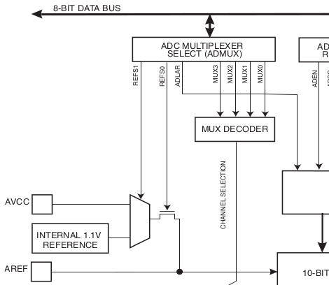
If you’ve used the analogRead() function then you’ve already measured a voltage using the Arduino. But do you know what is going on behind the scenes to make this happen? The Analog to Digital converter on the AVR chip is being used to measure an incoming voltage by comparing it to a known voltage reference. That reference is by default the supply voltage line for the chip. This should be 5V but will only be as accurate as the regulator supplying it. [Scott] looks at the other voltage references that may be used. An external reference can be used by adding hardware, but that’s not the focus of his article. Instead he looks at using the 1.1V internal reference. He’s written some short example code that let’s you measure the incoming line voltage based on that internal reference. This is a very handy trick that can let you detect when the chips is running from a battery and how much juice is left in the cell.


Five days after this HaD post – with zero comments. The masses have voted, Enough Arduino!!!
Using the 1.1V reference also allows using a different range of a sensor without changing pullup/pulldown resistors.