Laser Diode Controller For A CNC Mill

[Smells of Bikes] wanted to add laser etching to the list of tricks his home CNC setup is capable of. He has a diode which will work for the task, but he needed a driver that could be interfaced with the CNC system. He ended up designing a driver board based around the LM3402 chip.

Now driving one of these laser diodes isn’t all that different from driving a Light Emitting Diode. He chose to use the LM3402 chip because he’s the TI engineer who designed the official evaluation board for the part. It’s meant for high-power LED applications, and the 700 mA he needs for the laser is within spec. Since he’s soldering by hand, and this part has a ground pad on the bottom, he shares his soldering technique in detail. Once the driver board is ready, he uses a ‘sed’ command to replace the g-code Z axis commands with digital on/off commands to switch the diode.

Check out the demo video after the break. He uses a diffuse beam since the cutting beam is bright enough to damage his camera.

Continue reading “Laser Diode Controller For A CNC Mill”

Arduino Voltage Measurement Tricks

We think it’s a great learning experience to tear back the veil of abstraction and learn a bit more about the hardware found on an Arduino board. This project is a great example. [Scott Daniels] takes a look at the other voltage measurement options available to AVR chips used by Arduino.

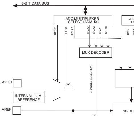
If you’ve used the analogRead() function then you’ve already measured a voltage using the Arduino. But do you know what is going on behind the scenes to make this happen? The Analog to Digital converter on the AVR chip is being used to measure an incoming voltage by comparing it to a known voltage reference. That reference is by default the supply voltage line for the chip. This should be 5V but will only be as accurate as the regulator supplying it. [Scott] looks at the other voltage references that may be used. An external reference can be used by adding hardware, but that’s not the focus of his article. Instead he looks at using the 1.1V internal reference. He’s written some short example code that let’s you measure the incoming line voltage based on that internal reference. This is a very handy trick that can let you detect when the chips is running from a battery and how much juice is left in the cell.

Mechanical Skeeball Built From Knex

We don’t really know what to say. This Skeeball cabinet is built entirely from Knex. It works exactly how you’d expect Skeeball to work. You plug in quarter and it dispenses balls and keeps score.

[Shadowman39] worked on the build for more than a year. Everything that went into it is a Knex part with the exception of a few rubber bands, and the paper numbers that are used on the scoreboard. There are six motors which drive the machine. Four of them are responsible for turning the scoreboard digits, the others handle ball return.

The link at the top starts off with a bunch of images of the various parts, but you’ll want to watch the video after the break for a closer look. It shows the coin hopper in greater detail. It’s built to only accept quarters and to reject all other coins.

Continue reading “Mechanical Skeeball Built From Knex”

Connect 4 Binary Clock

As part of a class at University, [Emacheen22] and his teammates turned an old Connect 4 game into a binary clock. This image shows the device nearing completion, but the final build includes the game tokens which diffuse the LED light. We enjoy the concept, but think there are a few ways to improve on it for the next iteration. If you’re interested in making your own we’d bet you can find Connect 4 at the thrift store.

Instead of using the free-standing game frame the team decided to use the box to host the LEDs and hide away the electronics. Since they’re using a breadboard and an Arduino this is a pretty good option. But it means that the game frame needs to be on its side as the tokens won’t stay in place without the plastic base attached. They used a panel mount bracket for each LED and chose super glue to hold all of the parts together.

We think this would be a lot of fun if the frame was upright. The LEDs could be free-floating by hot glueing the leads to either side of the opening. Using a small box under the base, all of the electronics can be hidden from view. After all, if you solder directly and use just a bare AVR chip there won’t be all that much to hide. Or you could get fancy and go with logic chips instead of a uC.

Automatic Speaker Control Via TV

[Jon] wanted his speakers to come on and off along with his TV. The speaker heats up if left on so he didn’t want to do that. But killing the power also resets the volume level (this is an old set of PC speakers and the remote is wired, not IR) so using one of those switched power strips was out as well. He thought a bit about trying to use the power LED on the TV to build his own circuit when it dawned on him. It’s possible to monitor the USB port on the TV and use it to switch on the speakers.

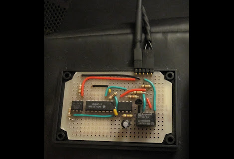
The circuit above uses a couple of opto-isolators to protect both the television and the speakers. The 5V line from the USB port on the back of the TV is monitored by an XNOR gate (which helps to filter out some of the toggling at power-on). When that gate latches it activates a 555 timer which in turn fires up the speakers. Presumable this happens when power is cut as well, but we’ll let you work through the circuit logic yourself.

Buying Cheaper Electronics And Not Saving Money

As an engineer at Spectrum Design in Minneapolis, [Carl] works with clients to get their product out to the masses. When designing a new USB-powered device, one client thought it would be a great idea to include a USB car charger with the device. The client promptly ordered a few thousand car chargers from China and everything was going swimmingly.

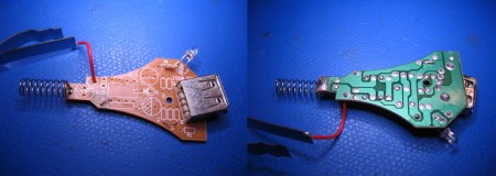
Everything was fine, of course, until [Carl] decided to test the Chinese car chargers with the client’s device. The USB PHY burnt out in short order, and the likely culprit was a shorted 12 volt regulator. This demanded a closer inspection, so after cracking open the charger [Carl] was amazed at what he found.

Yes, what you see on that circuit board is accurate. The manufacturer of these car chargers never even populated the switched mode regulator for this car USB charger.  Amazing, considering a single 10 cent 7805 DC regulator would have almost worked for this application.

If there was ever an example of being careful when purchasing the cheapest possible product to increase profit margins, this would be it.

Ever the engineer, [Carl] sent this into the tip line as a Word document. That’s available here, along with a slide show of the pictures [Carl] snapped.

Continue reading “Buying Cheaper Electronics And Not Saving Money”