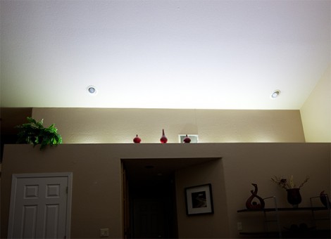
We see LEDs used in all kinds of projects but rarely does someone build a home lighting system from scratch with them. [Paulo Oliveira] decided to give the idea a try, included a fading power supply for the LEDs which he built himself. Here you can see the installation at full brightness, but his controller also offers a single lower setting.
We saw [Sprite_TM] use an RGB LED strip to light up his living room. [Paulo] went with individual LED modules instead, all the same color. They are Cree XM-L power LEDs so some thought needs to be put into heat dissipation. All six are mounted along an aluminum strip which serves as the heat sink. They’re wired in series and powered by an old laptop power supply. A PIC 12F683 uses PWM to dim the string via a MOSFET.
The control system for the two brightness levels uses the wall switch. When turned on, the LEDs fade in to full brightness. If you turn the switch off and back on before they are all the way on, the dimmed setting takes over. This was complicated by the capacitance of the PSU but [Paulo] solved that by adding a power resistor.


I think I’m most impressed by the ingenious way he decided to use the old switch instead of using pots/etc like most people would.
Not too ingenoious… I have seen lighting setups that do that already, you can buy them from SmartHome.com
right because it is soooo much more fulfilling to buy a comerical product than develop the skills to do something creative…Why do you come here again?
I think he prefers something new to be created. Some see it as re-inventing the wheel.
It’s fartface. You know he’s trolling you right?
Oh my. Electric lights have been around for over 100 years. You’re right, this “hack” is just a waste of time.
I think a good solution for the power off detection is to increase the timer duration.
Adding an extra load to make the adapter turn off faster goes against using the LEDs as an efficient light source.
Since the drop on the resistor is 1.7 * 0.5 = 0.85V i suggest using a linear constant current source that may be made by simply adding another transistor to the MOS driver and a heatsink. Like i suggest here, but with the resistor connected to the microcontroller output instead of battery
http://www.electrobob.com/wp-content/uploads/2010/03/fig4-mare.jpg
I like the article, and the simplicity of the build.
Like , I’d like to see a different solution to the ‘brown-out’ time of the laptop psu.
My approach would be to use the internal Vref (dont know if that is available in a PIC?!), and compare it to the raw voltage, possibly using a voltage divider, from the psu (not from the 7805).
That way I imagine it would be trivial to detect when the power is switched off, by simply looking at the voltage from the psu.
(i’ve done that myself using an arduino to detect if it was running from a battery, or running from a power supply).
Thanks for sharing!
the psu voltage might be stable for a long time while the capacitor that filters the mains will discharge.
most psus are 100-240V compatible, but i have seen some operate even from 48V if lightly loaded. untill the mains filter cap discharges enough you will see a stable outputo, so ypu cannot detect it like that.
direct access to the mains can do that, but it complicates things too much.
This is not a hack, it is mostly a fact, LED will rule the modern world. They are just pioneers!