Electromagnetic Interference For Fun And Profit

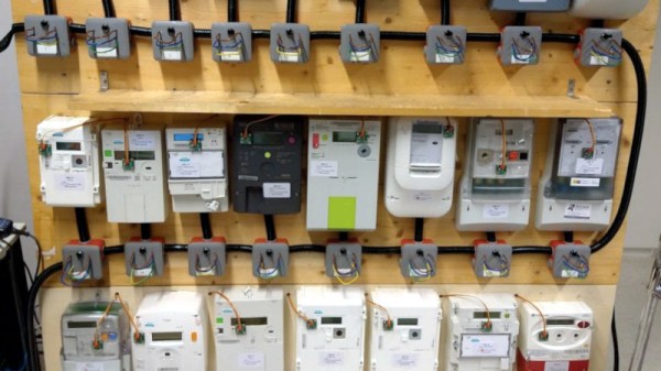
There was an urban legend back in the days of mechanical electricity meters, that there were “lucky” appliances that once plugged in would make the meter go backwards. It probably has its origin in the interaction between a strongly capacitive load and the inductance of the coils in the meter but remains largely apocryphal for the average home user. That’s not to say that a meter can’t be fooled into doing strange things though, as a team at the University of Twente have demonstrated by sending some more modern meters running backwards. How have they performed this miracle? Electromagnetic interference from a dimmer switch.

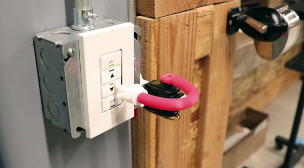
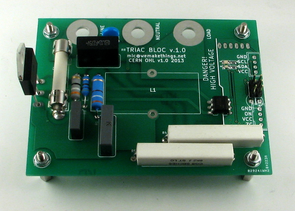
Reading the paper (PDF link) it becomes apparent that this behavior is the result of the dimmer switch having the ability to move the phase of the current pulse with respect to the voltage cycle. AC dimmers are old hat in 2021, but for those unfamiliar with their operation they work by switching themselves on only for a portion of the mains cycle. The cycle time is varied by the dimming control. Thus the time between the mains zero-crossing point and their turn-on point is equivalent to a phase shift of the current waveform. Since electricity meters depend heavily upon this phase relationship, their performance can be tuned. Perhaps European stores will now brace themselves for a run on dimmer switches.

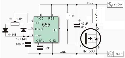
If you’re curious about these old-style dimmers, take a look at some of their basic functionality.

Thanks [Dorus] for the tip.

Teardown: Bug Zapper Bulb

Up here in the Northern Hemisphere, mosquitoes and other flying pests are the last thing on anyone’s mind right now. The only bug that’s hindering gatherings at the moment goes by the name of COVID-19, but even if we weren’t social distancing, insects simply aren’t a concern at this time of year. So it’s little surprise that these months are often the best time to find a great deal on gadgets designed to deter or outright obliterate airborne insects.

Whatever PIC stands for…it’s not that.

Case in point, I was able to pick up this “Bug Zapper LED Bulb” at the big-box hardware store for just a few bucks. This one is sold by PIC Corporation, though some press release surfing shows the company merely took over distribution of the device in 2017. Before then it was known as the Zapplight, and was the sort of thing you might see advertised on TV if you were still awake at 3 AM. It appears there are several exceptionally similar products on the market as well, which are likely to be the same internally.

In all fairness, it’s a pretty clever idea. Traditional zappers are fairly large, and need to be hoisted up somewhere next to an electrical outlet. But if you could shrink one down to the size of a light bulb, you could easily dot them around the porch using the existing sockets and wiring. Extra points if you can also figure out a way to make it work as a real bulb when the bugs aren’t out. Obviously the resulting chimera won’t excel at either task, but there’s certainly something to be said for the convenience of it.

Let’s take a look inside one of these electrifying illuminators and see how they’ve managed to squeeze two very different devices into one socket-friendly package.

Continue reading “Teardown: Bug Zapper Bulb”

WiFi Controlled Finger

WiFi Controlled Finger Dims Lights Over UDP

While WiFi controlled lights are readily available, replacing your lighting fixtures or switches isn’t always an option. [Thomas] ran into this issue with his office lights. For the developers in the office, these lights always seemed to run a little too bright. The solution? A 3D printed, WiFi controlled finger to poke the dimmer switch.

This little hack consists of a servo, a 3D printed arm and finger assembly, and a Wemos D1 Mini development board. The Wemos is a low cost, Arduino compatible development board based on the ESP8266. We’ve seen it used for a wide variety of hacks here on Hackaday.

For this device, the Wemos is used to listen for UDP packets on the company’s WiFi network. When it receives a packet, it tells the servo to push the dimming button for a specified amount of time. [Thomas] wrote a Slack bot to automatically send these packets. Now, when the lights are too bright, a simple message to the bot allows anyone to dim the lights without ever leaving the comfort of their desk. Sure, it’s not the most secure or reliable method of controlling lights, but if something goes wrong, the user can always get up and flip the switch the old fashioned way.

Light Dimmer Shows How To Steal Power From AC Line

We see a lot of traffic on the tips line with projects that cover old ground but do so in an instructive way, giving us insight into the basics of electronics. Sure, commercial versions of this IR-controlled light dimmer have been available for decades. But seeing how one works might just help you design your Next Big Thing.

Like many electronic controls, the previous version of this hack required a connection to a neutral in addition to the hot. This version of the circuit relies on passing a small current through the light bulb the dimmer controls to avoid that extra connection. This design limits application to resistive loads like incandescent bulbs. But it’s still a cool circuit, and [Muris] goes into great detail explaining how it works.

We think the neatest bit is the power supply that actually shorts itself out to turn on the load. A PIC controls a triac connected across the supply by monitoring power line zero-crossing. The PIC controls dimming by delaying the time the triac fires, which trims the peaks off of the AC waveform. The PIC is powered by a large capacitor while the triac is conducting, preventing it from resetting until the circuit can start stealing power again. Pretty clever stuff, and a nice PCB design to boot.

Given the pace of technological and cultural change, it might be that [Muris]’ dimmer is already largely obsolete since it won’t work with CFLs or LEDs. But we can see other applications for non-switched mode transformerless power supplies. And then again, we reported on [Muris]’s original dimmer back in 2009, so the basic design has staying power.

Making A Solid-state Relay With I2C Interface

As [Mic] often got requests to make high-power switching boards, he recently finally gave in and designed the one shown above based around a solid-state relay. Some of our readers that already play with mains power know that switching should normally occur when the voltage crosses zero volts. The ‘TRIAC BLOC’ is able to do so, which also allows mains frequency measurement. [Mic] then tuned to the internal oscillator of his ATtiny microcontroller with this 50Hz by adjusting its OSCCAL register value, so the switching command can be sent at the ideal moment. Zero crossing detection is implemented by feeding the mains into an AC optocoupler. [Mic] discovered that the optocoupler diodes are not identical, so he had to adjust his firmware to account for the time differences.

All the resources are available on github, we would be interested to hear your detailed analysis of the circuit implemented with the passives R3/C1/L1/R8/C3.

The Easy Or Hard Way To Build A PWM Dimmer

From what you would gather from Hackaday’s immense library of builds and projects over several years, the only way to do PWM is with a microcontroller, some code, a full-blown IDE, or even a real-time operating system. To some readers, we’re sure, this comes naturally and with an awesome toolchain it can be as easy as screwing in a light bulb. There is, of course, an easier way.

[Jestin] needed to vary the current on a small 12 Volt load. Instead of digging out an in system programmer, he turned to the classic 555 chip. With a single pot, it’s easy to vary the duty cycle of the 555 and connect that to a MOSFET. Put a load in there, and you have a very easy circuit that’s a fully functioning PWM dimmer.

If all you have are a few scraps in your part drawers, this is a very, very easy way to set up a dimmer switch. We’re also loving [Jestin]’s improv aluminum tube enclosure, as seen in the video below.

Continue reading “The Easy Or Hard Way To Build A PWM Dimmer”

Dimming LED Bulbs Designed To Replace Halogen Lamps

dimming-led-halogen-replacements
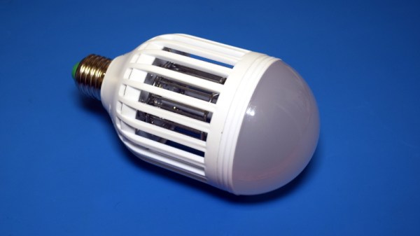
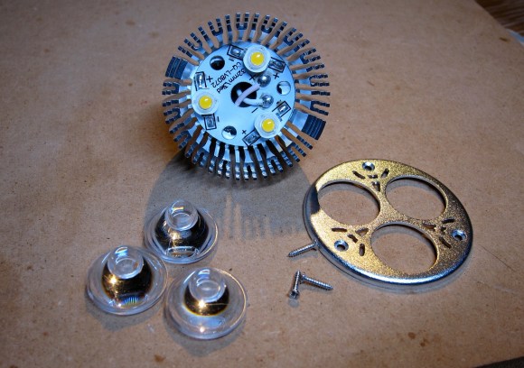
Halogen bulbs put out a lot of focused light but they do it at the expense of burning up a lot of Watts and generating a lot of heat. The cost for an LED replacement like the one seen disassembled above has come down quite a bit. This drove [Jonathan Foote] to purchase several units and he just couldn’t resist tearing them apart to try out a couple of hacks.

The one we find most interesting is a PWM based dimming hack he pulled off with an Arduino board and a FET. The bulbs are designed to be dimmable through the 12V supply that feeds the light fixture. But the relationship of dimmer position to light level is not linear and [Jonathan] figured he could do better. His solution is to add a FET in parallel with the LEDs. When activated it basically shunts the current around the diodes, resulting in a dimming. The video below shows this in action. We wonder if the flashing is a camera artifact or if you pick that up with your eye as well?

You may also be interested to read his post on Gelling the LED bulbs. Gels are colored filters for lights (or camera lenses). He cuts his preferred color down to size and inserts it between the LEDs and the lenses.

Continue reading “Dimming LED Bulbs Designed To Replace Halogen Lamps”