Most audio tube amps we see use common tubes – usually a 12AX7 for the preamp and one of the more common power tubes such as an EL34.[Daniel], on the other hand, decided to build his own audio tube amp with a 13EM7, a tube originally used for a television’s vertical oscillator. The resulting project is a wonderful stereo amp that sounds really good, to boot.
[Daniel] picked up the idea of using a 13EM7 tube from [Fred Nachbaur]’s MiniBlok SET amplifier. This very tiny 1-watt tube amplifier uses a single tube originally designed for use in old, old televisions. The secret behind this build is the fact this tube is actually two triodes in one package; one side of the 13ME7 has tons of gain but not much power, making it perfect for a preamp. The other side has a lot of power, useful for delivering two watts of power into a speaker.
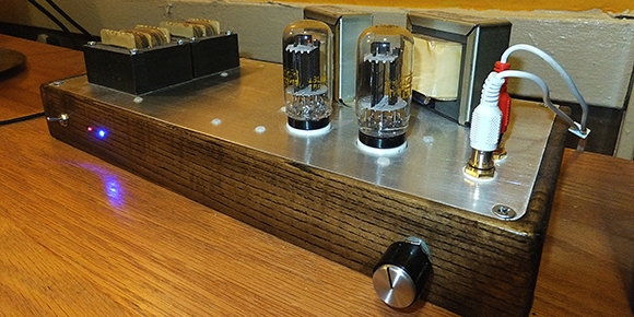
After [Daniel] etched a few boards for his amp, he milled out a piece of wood for the chassis. When everything was mounted he had an awesome looking stereo amplifier that also sounds great.


those coils on the left hand side, ever so slightly out of focus… made me wonder if it also made toast =P
I also thought that , didn’t read the title either so by glancing at the picture presumed it was some kind of tube amp toaster xD
The tube-amp toaster, perfect gift for the true toastphile in your life.
Don’t forget the 10 gauge, oxygen-free butter.
those are called TRANSFORMERS and they turn into robots, cool, eh?
Another misleading title, was expecting a specific tv tube, most all tubes, are diode, triode, was expecting something other than this. Up next on hack a day, DIY amp featuring plasma transistors….. John [doe] used a transistor from an old plasma tv he had laying around….
The 13EM7 is a TV tube – a tube purpose-built to be used in black and white televisions. It was only designed as an oscillator and vertical deflection amplifier. Using this tube in an audio application is actually a novel use for it.
It’s hardly misleading when the picture obviously lacks a CRT…
The title is the title and the picture is the picture, if the title is misleading then the title is misleading regardless of anything else.
I think most of us parse the title way before we parse the rest of the article and I, for one, also got excited thinking someone had figured out a way to use a CRT as an electrical amplifier.
I only have a vague idea of how’d you do that and it definitely looks dangerous but hey, this *is* Hack a Day, there *is* people smarter and gutsier than me in here.
it would be novel, if it wasn’t widely documented on the net already… this tube has been used and recommended for use in tube amps all over the nets, I agree, weak hack, just regular DIY audio….
How could you possibly think someone made an amp from a CRT?
Well, why not? CRTs are quite modulatable at decently high frequencies (a few MHz) and are capable of non-trivial current. The flicker of a CRT acting as an amplifier stage would be pretty damn cool IMHO, especially if you left the sync generators running open-loop, it’d plot a lovely amplitude-map of the music, rapidly shifting.
Someone must build this.
But if a CRT could be used as an amplifier, there would be no display on the screen. The anode in a CRT is unlike the plate in any other tube, I doubt you could get the electron flow from the cathode to go to the anode, so the electron can flow from the anode trough other circuitry before retuning to the cathode. I could be wrong, but I doubt there is a control grid inside a CRT to be able to control the electron flow through the CRT.
This is why you’d need a vacuum pump and some l33t glass-welding skillz! A CRT is a lot like a tube. Mr Gray, of Gray code fame, made a single-tube ADC using a deflection coil to move a beam across a Gray-coded plate. Perhaps have a variably-resistive plate where the screen goes, and use the deflection to move the electrons across it. Or abuse the focussing coil. Or something, I dunno, whatever it is it’s an opportunity for insane genius.
You’d put the output transformer in series with the anode of course. Sure there’d be an image, but it’d be middle grey with tiny variations with the signal; the beat ought to be visible as a flicker at least and if you get tones near half the horizontal scan rate, I’d expect to see moire-type interference producing a horizontal comb pattern. Of course there’s a grid – how do you think they modulate the electron beam to vary the brightness?
The real problem though is that your average audio tube runs at a couple hundred volts while a full-size telly runs at maybe 15kV. The output transformer is going to need an epic number of primary turns (and insulation!) so its inductance might be problematically high. It’s not going to sound good.
I’m really not sure how one would have electrons strike the screen to produce an image, while while diverting other electrons to other circuitry via the anode. Yea opening the CRT to make internal modifications would be a hack, but for most it is bench racing, as is using a CRT as an amplifier. AI recall the old rule of thumb for B&W TV was 1 kilo-volt per inch of screen measurement i.e. 25″ screen 25 kilo-volts, a color TV higher yet. Been a while since I messed with TV, and my old books are stored to deep to refresh memory
Beautiful build.
This is the original “one-tube” amp: http://www.atatan.com/~s-ito/amp/yakinori.html
The 6BM8 (European: ECL82) is a triode gain stage and a pentode power amp (7 Watts) in a single tube. Very pretty, very elegant.
Those TV tubes generally have poor linearity, since that doesn’t matter in the TV application. For audio use, it’s necessary to apply a lot of feedback to get low distortion, which this design does not do. You’ll notice that the designer doesn’t say anything about measured distortion.
Unless of course you want that distortion.
It’s not a guitar amp…
Tubes are not “voodoo” you can make an audio amplifier out of ANY tube. I have seen FM transmitter tubes used to build an audio amp.
I’m a little surprised he went with such inefficient power supplies, seems like he knows what he’s doing. Guess he doesn’t care that it doesn’t as a space heater? But those transformers could have been way smaller and fit inside the case.