Last time, we discussed how in-vehicle networks work over CAN. Now we’ll look into the protocol and how it’s used in the automotive industry.
The Bus
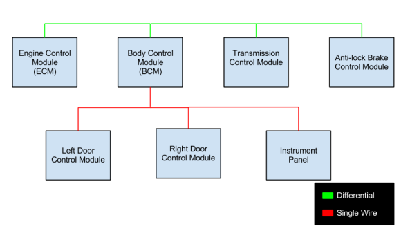
On the hardware side, there’s two types of CAN: differential (or high-speed) and single wire. Differential uses two wires and can operate up to 1 Mbps. Single wire runs on a single wire, and at lower speeds, but is cheaper to implement. Differential is used in more critical applications, such as engine control, and single wire is used for less important things, such as HVAC and window control.
Many controllers can connect to the same bus in a multi-master configuration. All messages are broadcast to every controller on the bus.
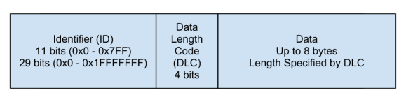
From a software perspective CAN message consists of 3 parts: an identifier, a data length code, and up to eight bytes of data.
The identifier (ID) is used to specify what the message means, and who’s sending it. Typically standard IDs are 11 bits, but there are also 29 bit extended type IDs. The ID also defines the priority: the lower the ID, the higher the message’s priority.
The data length code (DLC) is 4 bits, and specifies how many bytes of data will be in the message. In some applications, a DLC of 8 is always used, and unused data bytes are padded with zeros.
Finally, the 8 bytes of data contain the actual information. The meaning of the information is inferred from the message ID, and the length is specified by the DLC.
Decoding & Databases
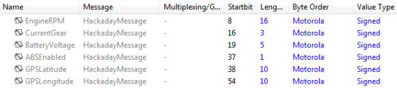
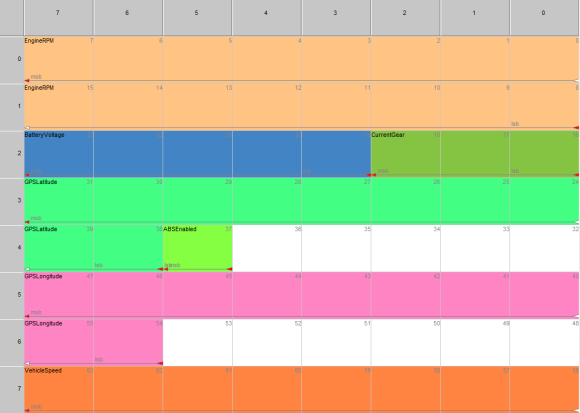
To make sense of the 8 data bytes, the controller will decode the data into signal such as engine RPM, fuel level, or brake pedal position. Each signal has a start bit and end bit, which are used to select the correct bits out of the 8 bytes. No signal information is transmitted over the bus. Instead all controllers must agree on the layout of messages and signals beforehand. Below is the table of signals, and the graphical layout of a sample message.
To help program controllers that agree on messages and signals, a CAN database is used. This database contains definitions of all messages and signals. The most popular format is DBC, which is a proprietary (but ASCII based) format by Vector. The DBC editing tool, CANDB++, is free (as in beer). The databases are used to auto-generate code that can interpret the messages.
With a database file in hand, you can easily sniff the CAN bus and interpret all kinds of data. One example is a hack we featured that sniffed the bus for steering wheel button presses. You can also pretend to be controllers by sending spoofed data onto the bus. For example, you could send a fake engine RPM to the instrument cluster.
The majority of the communications during normal operation work by decoding a database. However, for diagnostic applications, there are special protocols that are used. Next time, we’ll look at how these protocols work, and what fun can be had with them.


So where exactly do you get the DBC databases? I assume the manufacturers dont supply them.
There is no “legal chance” to get the DBC files from a car manufactor and the manufactores does not exchange DBCs between each other. There is no standard, because you can make conclusions about the build in sensors or other hardware.
It is also not allowed to drive cars with direct CAN access from outside the cars closed system on public streeds, but what you do on private ground depends on you. Only cars with special licenses can drive in public. But If you have CAN access, it is very easy to verify the CAN messages, by switching, pushing or whatever. You can push a button and look on the messages, what values changes. For example, the linux kernel have the VW/Audi SocketCan in it, til version 3.6.0. With the SocketCAN utils on:
https://gitorious.org/linux-can/can-utils/source/16c970d40e6c19dde705bad4751bab1a3a4f3a0d:
you have open source cansniffer, candump and canplayer utilities. It is very easy to analyse CAN messages.
Do you have a cite for it not being legal to drive a car with direct CAN access on public roads? What country does that pertain to?
I know that Europe and the USA does not allow direct CAN access.
That’s not really a citation, and to the best of my knowledge, not true. I know there are statutes that dictate one cannot view the data in realtime (much like anti-texting and driving laws), but even for safety critical systems, while ill-advised, it’s not illegal so long as you don’t impact federally mandated systems (e.g. emissions, in the US).
So scangauge violates the law then. Because mine access the canbus and they claim it’s legal. and yes it CAN change things like reset the SES light as well as other functions.
Databases are used by OEM and those close enough to the OEM to get access. Top level aftermarket ECU’s will sometimes include.dbc files again depending on who you are. I don’t know of any free tools what will use .dbc files, the most accessible I can think of Matlab/Simulink, again you need a few hundred dollars of hardware plus the software to get started.
Few hundred dollars? A ODBII bluetooth adaptor off ebay is more like 10. Works well with android apps.
Does that 10 dollar adapter integrate with Matlab/Simulink? Or does that android app support .dbc files? I’m talking about using putting .dbc files to use, not getting on the CAN bus for cheap, I realize that there are cheap CAN adapters out there. I have a cheap USB one connected right beside my Kvaser interface.
The cheap unit works great for monitoring the bus, however when you want to do anything more like isolating a node and filtering it’s data the professional interface is a must.
You actually can interface those adapters to MATLAB and other programs. The bigger issue is that accessing non-OBD CAN data is tricky and requires direct manipulation of the AT commands (e.g. in an ELM327). Both devices have their place.
You can put together a simple serial model that would interface with serial to CAN dongle, however to use .dbc files and VNT CAN blocks you need a supported device. Simulink is more than likely overkill for all but the top level guys that are doing real deep CAN bus work, like integrating aftermarket ECU’s into OEM applications. If you want to sniff the bus to roll up your windows with an Arduino there is no need to go down this rabbit hole.
The Arduino is not fast enough for all CAN buses, I struggled with the 16Mhz AT90CAN til i rewrote a lot of the atmel CAN routines. I found when i was logging i’d loose a lot of messages and not be able to reply fast enough. But saying that i am one of the “like integrating aftermarket ECU’s into OEM applications” guys, now it keeps up with all my ‘pro’ tools. There are a lot of decent ARM’s with CAN the STM32s spring to mind.
But logging is still logging, IMHO its better to go that little bit above to be sure you’re logging all the data, and replying fast enough.
But if you’re only sending out CAN messages or reading OBD II PID’s the arduinoish ones are fine, so use those for the final devices.
I once wrote a DBC parser in Python. It wasn’t too bad, since the format is ASCII based. Unfortunately, I lost it in a drive failure… this is before I learned that Git is a good thing.
I was hoping someone who say there is a community effort out there to document the CAN bus for various cars, especially since there is so much parts commonality between either model years, of various models of the same manufacturer.
GM and other actively sue groups like that into the ground. I was very active in a GM ECM reverse engineering group and GM not only threatened major lawsuits, but threatened that we would be in federal export violation of military equipment if we did not stop publishing our data and findings.
If you do create a nice document, publish it anonymously so the lawyers can not find you and do so on multiple sites so they cant squash it.
What group were you with? Used to do the same myself….
Check out Busmaster if you want a free CAN tool that can handle .dbc files. You need a pro hardware interface to use it though.
for diagnistic, if you have the dbc files, you can use https://github.com/rbei-etas/busmaster a free software of Bosch.
Depending on the OEM, canbushack.org (not affiliated with these guys) has some good tips. Madox.net has Mazda info, Swedespeed for Volvo, …
Your (link) is missing the link:
“Last time (link), we discussed…”
Indeed, thanks.
Really looking forward to the rest of this! Cant wait to have a play with CAN
wouldnt mind more info on these databases too, when i sniffed out the steerignwheel and i-drive controlls on my car i just bashed the buttons and parsed the logs untill i found something plausable, took a few days, and that was just for basic user inputs never mind interesting stuff like wheel speeds and central locking status and what have you.
How about a Wiki? Sparse now, but hoping to build it up. Would love to see what you’ve sniffed on your Bimmer!
http://vehicle-reverse-engineering.wikia.com/wiki/Vehicle_Reverse_Engineering_Wiki
Hey Denis, mind sharing the ID that you’ve found for the i-drive controls?
Also forgot to add the break. Although to be honest, I kinda like the idea of first article always being fully displayed…hmmmm
In addition to single-wire CAN and high speed CAN some people may also be interested in learning about CAN-FD. CAN-FD uses the same physical layer as highspeed CAN but the CAN controller allows a higher bitrate during data transmission allowing CAN-FD to be backwards compatible with highspeed CAN with higher datarates(currently around 8MB/s) or to transmit longer messages of up to 64 bytes.
For some more details on CAN-FD see:
http://can-newsletter.org/assets/files/ttmedia/raw/30e0cfdc05de5f831221487388087eb8.pdf
http://www.vector.com/portal/medien/cmc/events/commercial_events/VectorCongress_2012/VeCo12_8_NewBusSystems_3_Lindenkreuz_Lecture.pdf
Suppliers won’t give you there dbc files or CANdB Files. But it is common to just listen for some changes on the bus. Since every can node has a own Id you can just connect to the bus (most common is Baudrate 500k (then 250k and 125k)) so grab the steering wheel e.g. and turn it. With a small tool like PCAN VIEW, Vehicle Spy you can see the data changes. If there is a field which might have the data you want to see inside, try some filters like datasize 32bit or 8 bit and use different formats try two’s complement and tada we got the value of a Hyundai sedan in less then 5minutes. That is what companys do for testing parts of vehicles.
Also note, data size is not fixed to 8Byte, that was years ago, look into the framed messages and there is also CAN-FD.
For diagnostics things get more difficult since the ECUs wait for commands to send there data and there is a exhaustive use of protocols, like XCP, CCP…
Looking forward for more of this stuff. Thumbs up.
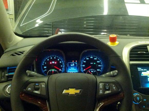
Also, why on earth is there an emergency stop on top of his dashboard?
I bet it’s a conversion to a autonomous-driving car. There the emergency stop makes sense if the car starts to act crazy ;)
It’s a prototype vehicle… the e-stop is a nice feature.
Why is there no break?
It does seem to clog up the front page a bit, huh? Added.
Most car manufacturers use the ASAM ODX standard for databases and there are multiple implementations of it…vector being one of the implementors. These databases contain everything from communication parameters to ecu variant identification templates to compute-methods for data sent on the bus. Most of the generic auto-shops out there use simple software provided by ECU manufacturers(eg. bosch, siemens) and grant access to simple DTC info and error memory info. Flash sessions or variant coding for instance require elevating the diagnostic session through a key and also much deeper manufacturer-specific knowledge.
There are multiple things that happen over the automotive networks.. there is the normal communication between ECUs (how fast am I going? are the doors open? what is the steering wheel angle?). The standard format for documenting the format of these messages is a DBC.
ODX or CDD (Vector CANdela) describe the diagnostic databases, i.e. what you can query using an external tool. These would be extremely helpful if they were released because they contain all of the diagnostic services (not just the legislated ones), and define all of the DTCs.
A2L is a lot more useful (for ecu oems that use it), those are the holy grail.
Someone gave me a joystick off of an electric forklift. It uses the CANbus, now if I can only figure out the proper wiring so I don’t let out the magic smoke when I go to test it….
Oh, you’ve just reminded me that I should talk about how CAN is wired in a future post. Usually the DB9 connectors use pin 7 for CAN+ and pin 2 for CAN-.
HSCAN is also standardized in pins 6 and 14 on vehicles with an OBDII connector (and that have an HSCAN network of course!)
I’d definitely like a post on wiring/connectors.
I’ve only worked with it briefly, but for the machines I was working on, we used these god-awful Deutsch connectors.
Bulky (for the number of wires), expensive, and only attached to the delicate wires, not the tough outer plastic/rubber sheath of the cable (wire bundle).
I’d like to see the other stuff that gets used, what’s common, what’s standard, what’s not, etc.
How did you plugin the CANbus on the car? I assume it’s all well protected?
The OBD2 port which is present on every car in the US from 1996 onwards.
This comment isn’t about the content, but more on the way it was presented. On the homepage of HaD, it looks like there is a double post of sorts. The bold green in the actual article is almost the same as the post name itself. Thought it was a bug at first lol. Maybe make the article section headers a darker green or something. Anyway, haven’t made a post since the new overloards. I like the direction and what is being done. I see more and quality things here and am welcomed to the changes.
Next up, MIL-STD-1553?
There is basic info on the standardised OBD diagnostics parameters here.
http://en.m.wikipedia.org/wiki/OBD-II_PIDs
If your looking to play around it is a good place to start.
The note i’d add to this is to take away the focus on 8 bytes, that’s just what the underlying CAN protocol is using
From a diagnostic/reprogramming software point of view, ie where we’re looking at it from, the actual message from the cars systems can be considerably longer, usually it is ISO 15765-2/ISO-TP the message is broken up into 8 byte packets, carrying 7 bytes of information, then typically reassembled inside the j2534 software and presented to the host software. look up CAN multi-frame message on wikipedia for details.
Nearly all reflash tools use multiframe messaging for instance, but if its via J2534 then it takes care of it, you can send long messages into J2534 and it’ll just split it up into multiple CAN frames, and reverses the procedure for incoming.
This is a subject very near and dear to our hearts here at @CarKnowLLC. We create CAN/GSM bridges (we call them “CARduinos”), but even with access to CAN — you really need an understanding of what exactly is on the network to accomplish anything.
On our company website (I don’t want to linkspam, so Google us), we have a link to a Wiki we’ve created in the hopes of building a user community for sharing reverse engineered CAN parameters. While it’s rather sparse now, we have more data that we’ve collected internally and hope to publish soon. We hope you join us in doing the same, so that we can all access the information transmitted within the vehicles we own and operate. There’s a lot of great potential here, and who knows — if we get enough user interest, we might be able to sway an OEM or two to the dark side.
Happy to opine, discuss, etc. if anyone has questions our company can help with. The hardware should be available for preorder shortly, either directly on our site or as part of a crowdfunding campaign.
With all the various gadgets that can be added to a car these days by home brew enthusiasts, I think a most useful CAN bus hack would to make use of a car central information display. It would guess a limitation would be that every manufacturer, or even model of car would need unique addressing.
I’ve been playing around with my 1 series BMW for a while now (I wanted to use the steering wheel buttons to control my carpc), and there’s a couple of things I learned.
easiest way to find the messages you want: record everything while on a drive to get a rather detailed list. then record everything again while in this case pressing buttons. then make use of the fugly mess of data you produced.
lists with IDs for specific cars may or may not be available.
the hardware i used for this is a custom design atmega32u4 / mcp2515 / mcp2551 board that runs in listen only mode and blasts all the data to the pc via a virtual com port. speed might be an issue, but the kcan on this car runs at a mere 100kbit.
i forgot to mention that i actually succeeded in finding the ids.
i then replaced the software. on the pc side it’s a simple hid now…
Isn’t the single wire one LINBUS? If it is, they are totally different kind of toys..
EcoCAR!
On the 2010 Ford Fusion SE model, it has a narrow LED display for radio and time display. I wanted to try and use my arduino and program my own display data there. Would a device like this Sanyo Automedia product, 9E5T-19C116-AE, (http://www.ebay.com/itm/09-10-Ford-Fusion-Infomation-Screen-Monitor-9E5T-19C116-AE-Bulk-4018-/360840349186?_trksid=p2054897.l4276)
be communicated with via CAN protocol (does the LED itself interpret CAN signal?), and could I wire directly to it from my arduino UNO and with software/libraries be able to display text on screen?
Or at this level does talking to the LED display have nothing to do with CAN and would be more like talking to the display driver, like an LCD Hitachi HD44780 driver?
hi,I would like to ask how can we find out the engine torque?since there are many torques in the CAN, such as driver torque, torque without request, ect, to find the them and give them a ‘correct’ convert formula is always a headache to me..
That is the reason why CAN Protocol was currently switching to Ethernet protocol. Now it is 2015, the Autosar architecture is implemented, built and burned as a program binary on chip as every client specify what modules from it want, to allow a boot loader to start this program in ECU’s without using CAN communication module activated, instead using Ethernet packets what are encrypted using SHA-128 cypher. Hard wire debugging will be harder, and harder like you try to intercept a raw decrypted GSM traffic using a 0.1 – 1 Mhz range antenna. Another implemented stage is signal norming which is a module what redirect a direct ECU -> Sensor[N] to a more complex route to make this game more fun. Have fun to play with cars above 2015.
I forgot to mention that I use a professional debugger hard (CANextender) and soft (CANoe) available from Vector, and a JTAG Debugger from Lauterbach that makes me able to media convert packets and switch between CAN/Ethernet protocol with help of a Cisco router to monitor the packets using Wireshark.
there’s nothing really special about them, as long as it can sniff can, handling timing and stuff they’re all pretty much the same, unless you rely on their software. i see people spend a fortune on whats often a can transceiver + mcu.
same for lauterbach, i have their trace32/+ BDM/jtag debuggers and simulators, they’re gathering dust since the software is subpar. better off saving the money and using a cheaper jtag (even pe micro) and spending the money on more tools or software dev. sure if you’re doing flash emulation they’re good upto a point. rolling your own tools, and spend money on idapro/winols etc.
cars have already been encrypted with RSA 512/1024 and never matters, i hear people decry all the time how hard its gonna get, cept they never factor in the human factor, people leak the keys, get bribed , take the software to their new gig and then it gets out, or just give it away. social engineering will always plug the gaps RE can’t. spend 5 minutes on any of the tuning boards and you’ll find docs/software and source for pretty much every ecu out there.
remember professional just means you paid for it
Some CAN Hacking for BWM iDrive:
https://youtu.be/zhwJLgnTy70
hi, can you please give a sample CAN database file for my research on controller area network?
Hi
I want to sniff the steering angle from my BMW 328i 2013 using a can interface(Ginko USB-CAN Interface),any ideas on how I could do that?Sort of lost..
I’m looking for a way to find out seed and key algo for my ecu, I have a2l and odx for it, there are a way to extract the algo from this file?
That information is not available in those files, assuming you’re talking about the service $27 key algo. The algorithm is generally very guarded by the OEM. Additionally there are constants unique for each ECU, which you would also need to know.
Yes i’m talking about service $27, Any other way to find out it?
You’re looking in the wrong place, the right place might be available but it’ll depend on what ecu/car you’re talking about.
the a2l/odx doesn’t usually contain any of that info, you might get memory addresses from it but thats all
marelli 6f3, but interested also on tricore.
like on a fiat ? , realise that oem’s can change keys/seed algorithms for the same ECU type on different cars. so the less information you give, the less helpful results you’ll get.
if its a fiat , grab the fiat reprogramming software, reverse it, find the checksum routine and that is all you need to do, supply that to the kwp2000 challenge/response.
its probably got a m58bw in it, and depending on which OEM’s flash chip is in it , depends on what you can and can’t read with it with most of the auto bdm’s but will witth proper bdm/jtag’s, or remove the chip
You probably want to be able to JTAG it since if you’re trying to write to it via kwp2000, you’re not unlikely to get it right the first time and though they have fall back recovery modes usually, if you fudge the memory block you’re reprogrammingerasing, you might wipe that out
as for tricore if you want to reflash those, they often have locked bootloaders and you’ll need a leaked key or use the boot pin trick and JTAG it. pretty most of the tricores have a tool set for them. but you’re starting off on the hardest ones.
Fiat marelli 6f3 is my first target, I already have checksum algo for both. Already try to disasm file from micro but without find seed and key(i know there is but disasm is not my bread). I have tool to r/w by obd and bdm/jtag.
so you have a few choices,
find it by RE, either in the ecu or the host reflash software.
find someone who has already done it and is willing to give it to you(sounds like you’re trying to make your own obd2 reflash sofware),
use one of the existing tools.
it’s a well known ecu/checksum but it’ll be hard to find someone just willing to give it up i’d bet. since most are using it commerically
Jhonny,
depending on manufacturer, I may be able to help you.
…go on
Currently I’ve been trying to reprogram my instrument cluster for information display changes.My current project is on a Toyota Corolla 2014. Current information display have the following options available to the user:
Average Fuel Consumption
Cruising Range until empty
Trip Elapsed Time
Average Speed
Realtime Fuel Consuption
Setting (for brightness etc)
The display cluster is controlled by a single button for switching displays. My project consists of changing ( or possibly ) adding a menu. For the displays that is subject to change, I want to replace the Average Speed display to Current Speed. Also, if possible, I want to add a menu for displaying Engine Load and Voltage Meter.
How can I reprogram the display on the LCD instrument cluster? Can i do it via OBD2? Also, what tools do i need? Any feedback would be greatly appreciated. Thank you.
Having figured out some data on a GM 2011 Terrain steering angle sensor for another project, I’d like to make it available and figure these comments might be a good place for people to find it. I’d appreciate suggestions for any better place to put such data.
GM Steering angle sensor PN 25849366. Pins 1&2 CAN-, Pins 3&4 CAN+, Pin5 12V, Pin6 GND. XXh indicates hex values. CAN, 500k, ID 0x180 packet every 10ms.
Byte 0, some sort of status: Junkyard sensor showing 4Eh, new part boots at 4Ah then 0Eh.
Bytes 1&2 are hb/lb of a signed 16bit angle. About 16 counts per degree. Measures +- 5 turns, power-cycle-stable values.
Byte3 (bits 31 to 24) 31=on, 29&30 are a 2 bit cycle counter, 28 off. 24-27 high nibble of 12 bit signed turning rate combined with Byte 4 as the low byte.
Bytes 5&6 similar to 1&2 but with reversed polarity, seemingly measured separately, slight variations.
Byte 7 is always 00h.
My hope is that this may help someone looking for data as I was. In this project I’m looking for a sensor to replace a Tesla steering angle sensor with a much smaller one that can be hidden in a classic car conversion. Translation will be required. I may not use this one, but it was fun to analyze anyway.
-Otmar
Is a master CAN DB of a major car manufacturer of any value at all? I’m not saying I have access to it, just curious.
there is value to it, a few companies sell it already but the OEMs have had issues with people selling the info once it gets to a big enough level, especially if they think you just pulled it off their tools.
Where do you think one can meet such prospective buyers? And what do you mean when you say “BIG ENOUGH LEVEL”?
well the biggest customers are generally OBD II scan tools etc, which are all mostly out of china these days. for smaller scale stuff, you’ll find them at trade shows like sema, then lower than that then its spread over the various car hacking forums. there is a lot of people in the security side who look for info, but they’re generally only interested in stuff that helps gain access than finding out your long term fuel trim. they already have a lot of that data anyway, and they’re not paying much for it, the us bound ones are buying from existing agencies that have long term relationships with the automakers.
but that is the question isn’t it, how small enough do you have to be before they’ll take notice, these days it seems like more how well known/social media you get, versus amount you actually sell. the smart ones stay quiet and go under the radar and choose not to poke the bear.
if you start selling it enough where the taxman is interested, that is probably the tipping point. socially its just when you stand out a bit more than everyone else and can be made an example of, those are the unluckiest ones.
How can I contact you?
Hypothetically, might be of value, Could discuss offline…..
Sure, but how?
How can I contact you?
pcmman@yandex.com
Email sent
Reading comments with great interest and trying to comprehend the interactions on the can bus. The reason is actually not automotive, but to use a component outside the automotive environment. Specifically, there have been several articles over the years that demonstrate how to use an epas steering system on older cars when restored. Some systems IE: the Saturn Vue, is used with an aftermarket kit that somehow simulates bus traffic to the steering ecu .
Some of these systems have been converted to be used on small tractors and work well in that mode. There is one person who has named several systems from several Japanese and Korean cars that will run in what he calls a “fail-safe” mode without any connection but the column motor to the ecu and no can bus. He states that he has not found a GM unit that would work out of the vehicle. I would think if one could emulate the required messages (if you can figure out what they are) to activate and allow the system to run . This is where my interest lies. I have an older Gm unit from a Cobalt I’m trying to figure out to use on my tractor to make the steering easier when the front loader is full. Any comments or suggestions would be greatly appreciated.
Hi. Just noticed your post. I’m trying something similar – use an EPA’s system as a torque multiplying device with input torque from a standard r/c servo. I have an epas from an Opel Corsa D, which has a 10 pin connector for canbus. I can’t find any info, like pinouts, so I’m just going to have to prod around to see what I can find. I just want to get it active, no need for speed sensitivity.
Did you make any progress with yours?
Take a look at https://medium.com/@comma_ai/a-panda-and-a-cabana-how-to-get-started-car-hacking-with-comma-ai-b5e46fae8646
I’m using the panda and cabana to track all the can messages and record the drive on the phone. The cabana software is incredibly neat at viewing the messages and trying to figure out what they are.
Could I use one of these to intercept CAN messages for brakes, indicators, reverse and lights?
This article is translated to Chinese and published as below but the translator doesn’t credit the original author. http://www.nsoad.com/Article/Vulnerabilityanalysis/20160903/346.html
Thanks! I’ll pass that along to our lawyers. We get copycats all over the world, but this is the first one that I’ve seen in translation. Neat.
(And of course, in violation of copyright law.)
Could I ask what are the difference between diagnostic signals and database signals.
When I’ve connected OBDII port , datas are diagnostic signals or database signals?
Also I can read the datas via PCAN view but how could I convert them readable form or how can I understand which message from which ECU .
Do you have any book or document about it could you share with me.
kind regards .
You can mail me about it. pinaradsiz@gmail.com
I have a question related to the CRC handling of CAN messages. As we know that CAN controller used CRC for error monitoring of received messages.
1. Is it possible that a ECU receives the CAN message without the CRC value? For eg. a spoofed CAN message sending directly the raw CAN message with correct CAN ID.
2. How is the CRC calculated for CAN? Are the generator polynomial used standards and available open source? like for CRC32,CRC64, etc.
3. So if I can sniff the CAN data(with CRC) and I extract the CRC from data , can I reverse engineer to get the CRC generator polynomial?