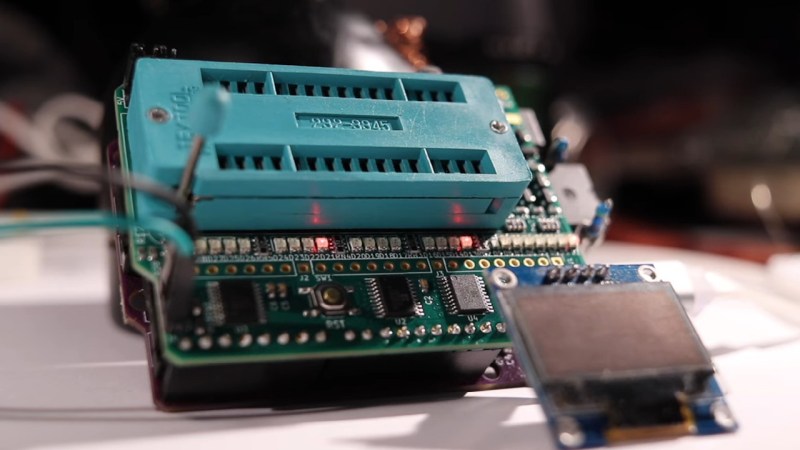
There’s treasures hidden in old technology, and you deserve to be able to revive it. Whether it’s old personal computer platforms, vending machines, robot arms, or educational kits based on retro platforms, you will need to work with parallel EEPROM chips at some point. [Anders Nielsen] was about to do just that, when he found out that a TL866, a commonly used programmer kit for such ROMs, would cost entire $70 – significantly raising the budget of any parallel ROM-involving hacking. After months of work, he is happy to bring us a project – the Relatively Universal ROM Programmer, an open-source parallel ROM programmer board that you can easily assemble or buy.
Designed in the Arduino shield format, there’s a lot of care and love put into making this board as universal as reasonably possible, so that it fits any of the old flash chips you might want to flash – whether it’s an old UV-erasable ROM that wants a voltage up to 30 V to be written, or the newer 5 V-friendly chips. You can use ICs with pin count from 24 to 32 pins, it’s straightforward to use a ZIF socket with this board, there’s LED indication and silkscreen markings so that you can see and tweak the programming process, and it’s masterfully optimized for automated assembly.
You can breadboard this programmer platform as we’ve previously covered, you can assemble our own boards using the open-source files, and if you don’t want to do either, you can buy the assembled boards from [Anders Nielsen] too! The software is currently work in progress, since that’s part of the secret sauce that makes the $70 programmers tick. You do need to adjust the programming voltage manually, but that can be later improved with a small hardware fix. In total, if you just want to program a few ROM chips, this board saves you a fair bit of money.


This is great! If you just need to do a ROM or two, you may also be able to use flashrom with a network card like a 3C509b that has a socket and can program up to 128K ROMs. I just did that recently and it worked fine.
But this looks much better, and most people won’t have such an old network card and a machine to put it in.
An old ISA network card is also great for playing around with DOCs (Disk on Chip) modules.
I use the Willem based programmer – GQ4X4. Will program just about anything.
But he said he didn’t want to spend the $70. I solved that problem by having my employer buy it for me.
EEPROM pr0n!
This reminds me of a similar project (afterburner, https://github.com/ole00/afterburner) for reading/writing similar chips, GALs, as sometimes used in 1990s equipment
Here are couple more projects that are helpful for programming and checking reto stuff.
I did a breadboard programmer with areduino mega. higher voltage was needed for the uv chips.
dram tester https://forum.defence-force.org/viewtopic.php?p=15035
spld programmmer… micro 8088 ATF16V8B https://github.com/ole00/afterburner
would be very cool to integrate all into a arduino shield.
Must be one of the shortest-lived products ever featured on Hackaday. Added to the website on Friday 19th, and now on Sunday 21st it is marked as discontinued! Must be a Hackaday Effect.
(To be fair, it is also marked ‘enquire anyway’ so there is probably hope for the future).
They sold, what can I say :) More coming, so I opened up for backorders.
This is how so many of my projects go, too. Didn’t want to spend $70, so spent months and 4 times as much (in the end) trying to come up with my own solution. And let’s be honest, in the end, this cost the author more than $70 to finish. We all fall into that well. Not knocking it!
And it isn’t going to cost just $9. The Arduino is more than that. That ZIF socket is close to that. The PCB would cost you more than that. Hell, the shipping on the parts would cost you more than $9.
My only gripe with the TL866 II is that there is no way to add your own algorithms and the programming voltage is too low for some retro parts. That would be the only motivation I would personally have for spinning my own solution versus just buying something that just works and I can move on. I know that isn’t in the spirit of hacking, but for me, anyway, I rather spend that energy actually hacking the thing I needed to build this for.
One of the things that has been incredibly useful to me in the TL866 software is the IC tester. I have been able to make my own tests for chips and also tests for my PAL, GAL, and CPLD designs.
The Arduino is something you are likely to have already, you can use a DIP socket instead of a ZIF socket, so, that cost is indeed for the PCB! Now, I’m not sure how the author came to this figure, maybe it’s ordering in 5pcs qty, maybe it’s a BOM cost, but it looks realistic to me. And, yeah, proprietary stuff being unmodifiable is frustrating, part of why I’d use such a programmer!
Re “no way to add your own algorithms” – not so: have you seen https://gitlab.com/DavidGriffith/minipro/ ? Even starting to have some support for the newer T48 model.
This is just a client that talks to the TL866 over USB. To support new chips the driver must be added to the FPGA inside the TL866. This hasn’t been done in opensource to my knowledge.
Ch341a bios flashers don’t support EEPROMs?
Those do SPI and I2C EEPROMs, not parallel ones, to the best of my understanding
Thank you for the nice writeup, Arya :)
YouTube decided it was a good idea to show the video to quite a lot of people, so the relatively few boards I had expected to sell in a couple of weeks, disappeared.. Let’s just say quickly.
..and @Retroplayer: Yes, sold for exactly 9$ + socket, headers and shipping. If you can live without the ZIF, the cost of a 32 pin socket is almost negligible. And I certainly didn’t spend much building it that I didn’t have on my desk already – unless you count my time that I otherwise would’ve spent on some other retrobuild :)
More coming, with the intended green LED’s – so I opened up for back orders.
Unfortunately this programmer has the same shortcomings as practically all offerings in the 2-digit price range: Vcc is fixed to 5V. Many parts and their programming algorithms require different voltages during programming and verify. For example, the W27C512 EEPROM wants 3.75V for erasure verification and the Am27C512 UV-EPROM wants 6.25V for programming and 5.25V for verification. It will usually appear to work with 5V, but “bit rot” will occur within a couple of years and not decades. Also a variable Vcc can help in recovering the contents of already rotten old EPROMs, a valuable feature if you are messing around with retro stuff or repairing industrial gear.
I don’t think that’s correct at all. He has a step-up that makes 30 V.
He’s actually pretty spot on about VCC :)
Some of the ROMs recommend or require a normally out of spec supply voltage to verify a byte is actually written, in addition to high programming voltages.
Basically – without double checking with out of spec operating voltage you can’t be 100% sure it’ll last as specced.
But if you’re going for a 9$ programmer, you’re probably more interested in the 14-21V that’ll just get your bytes written to begin with, and maybe less the 100% reliability checking.
If you wanted, you could manually vary the supply voltage of the whole shield.
If you want more reliable I imagine you’ll get the same by running the programming cycle twice.
To vary VCC I’d need a second regulator and drivers, which adds complexity and cost.
If you’re going for 100% within spec on a 30 year old ROM, I wouldn’t be so sure even a 50-70$ programmer could help with that anyway.
This served my needs for the hv chips I burn and it was relatively small cost to build as well
https://www.mattmillman.com/projects/hveprom-project/
In 1991 the cheapest programmer that would do what I wanted was £1000 so I made one that plugged into the edge connector of my ZX Spectrum. So it had a user interface, stored the data on cassette tape and could program two at a time up to 32k each. It cost me £90 to make at the time. It was also a nice little project for me as I was just starting out as an Electronic engineer.
Too bad. Still doesn’t program the 1701 and 1702 eproms. :) Need 47V and 59V for programming those. ;)
So this will burn MCM68764 or MCM68766 HV chips?
I’ve been using the open-source kit below for burning them. It can use an external power supply for high voltage. But it’s always nice to play with something new.
Does the upconverter here supply enough current for HV or does this need to be plugged into a 3A USB source?
Also – did I miss something? How do I get binaries into this?
https://www.mattmillman.com/projects/hveprom-project/
Yes, it shouldn’t have a problem with those – but you will have to swap out a single resistor.
Software is WIP – see end of video.
I made one for dome old prom 82S128 style.
https://github.com/Franck78/BIPOLAR-PROM-PROG
Firestarter is a cmd line app and fw that supports several 100s of PROMs
https://github.com/henols/firestarter_app