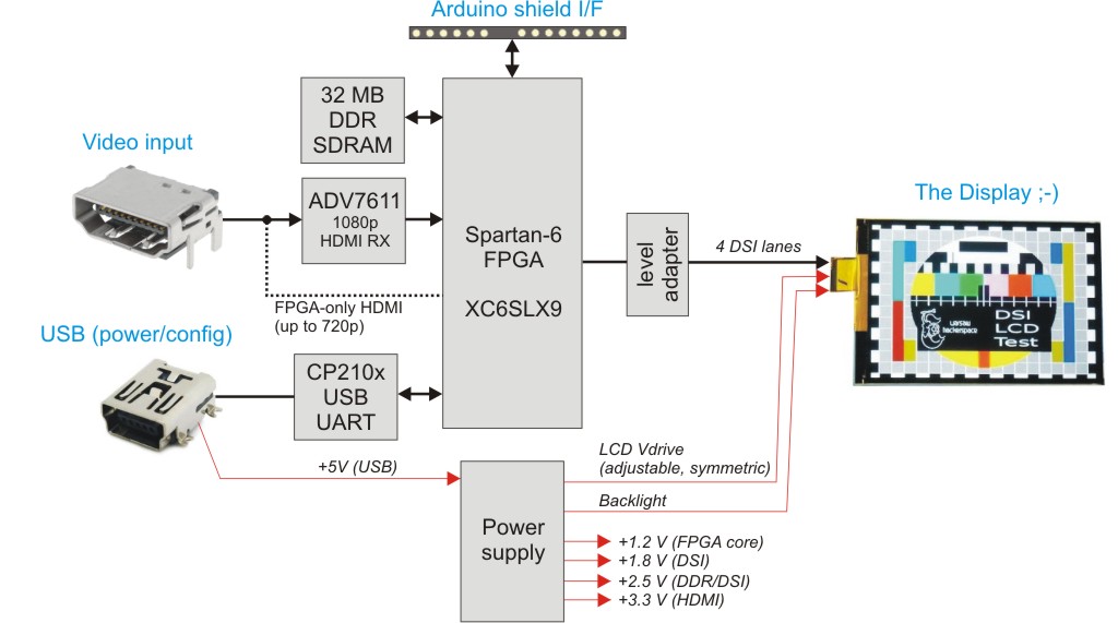
[Tomasz] tipped us about the well documented MIPI DSI Display Shield / HDMI Adapter he put on hackaday.io. The Display Serial Interface (DSI) is a high speed packet-based interface for delivering video data to recent LCD/OLED displays. It uses several differential data lanes which frequencies may reach 1 GHz depending on the resolution and frame rate required.
The board explained in the above diagram therefore allows any HDMI content to be played on the DSI-enabled scrap displays you may have lying around. It includes a 32MB DDR memory which serves as a frame buffer, so your “slow” Arduino platform may have enough time to upload the picture you want to display.
The CP2103 does the USB to UART conversion, allowing your computer to configure the display adapter internal settings. The platform is based around the XC6SLX9 Spartan-6 FPGA and all the source code may be downloaded from the official GitHub repository, along with the schematics and gerbers. After the break we’ve embedded a demonstration video in which a Raspi drives an iPhone 4 LCD.


Adafruit, please begin stocking this NOW.
Beats the heck out of PiTFT, which doesn’t even work with the present Raspbian build.
Definitely the best comment ! Shut up and take my money !
Funny how people here love to ignore the merits of cost. I see the PiTFT costs $35 (assembled, functional and including the TFT screen). The RaspberryPi’s core appeal is it’s price, and that transitively applies to its peripherals.
In this build, and checking just Digikey, the Spartan XC6SLX9 FPGA is $18, the CP2103 is $3.7 (per unit, discounts apply for larger), the ADV2611 is $15… oh woops we’re already at $36.7 in core parts alone, plus iPhone 4 screen he used in this project ($32 on eBay), oh whoops we’re already at $68.7 in core parts alone, and I’m not counting the cost of the powersupply, RAM, DDR, misc components. Add to that PCB manufacturing and assembly, then eyeballing it for development cost, failure rate, and margin, I’d be impressed if they’d be able to sell this under $150.
Would you still be interested at price?
I can’t believe you’re even trying to compare the 2.
The PiTFT is only 320×240, and uses the SPI port to send data to the screen.
When a product doesn’t suit your needs (eg, I need higher resolution and my SPI port is already in use), it doesn’t matter a damn if it’s cheaper !
If the RPi Foundation and Broadcom actually do something about it then you wouldn’t even need this board. The RPi SoC and RPi PCB itself both support MIPI DSI displays. We’re just missing the necessary VideoCore driver. The problem is the same as the RPi support of MIPI CSI camera in that you’d need to tailor the driver to the specific camera/display used as the commands aren’t standardised. If the MIPI DSI interface is ever used then it’d be most likely that you’d be locked into using 1 specific RPi Foundation approved module.
Why? All it needs are some parameters to set the resolution, clock rate etc.
>The problem is the same as the RPi support of MIPI CSI camera in that you’d need to tailor the driver to the specific camera/display used as the
>commands aren’t standardised
no, the problem is broadcom hubris and clinging to closed source solutions
there is ZERO reasons for keeping dsi/csi interface secret and closed.
with camera we got one off solution tied to one particular sensor because broadcom engineer decided “color correction and sensor initialization is too difficult for you arduino retards”
all we need is a DMA + memory mapped buffer that gets transferred to/from csi/dsi, not proprietary closed hidden in the binary blob solutions.
This device is more than just a display adaptor it also allows video in over HDMI. Now the question I have is can it act as a Genlock?
Yes, I would be interested at $150, if that included the price of an iPhone 4 display. You pay for what you get. Available “small” HDMI monitors are clunky and still cost >$150 (Adafruit), and still don’t match the clarity and resolution of the Retina display.
And how can you compare the beautiful Retina display with the crappy, slow, 320×240 PiTFT? At the latter resolution, I might as well use a 1998 LCD TV with a composite input!
What I want this device for is a mobile “heads-up” ham radio project. In a car, the brightness, clarity of the Retina display works well. I know, I use my iPhone in that environment all the time. This board has an overlay capability, which would be nice for this application, and I have not seen that feature in available small HDMI monitors. Yes, the Pi could overlay text for an “OSD” type look, but my Pi’s resources are very nearly all consumed with my ham radio application.
“CP2103 is $3.7 (per unit, discounts apply for larger), the ADV2611 is $15”
Both of those parts are optional. I already have a USB to UART cable, and the Pi could be used to configure the FPGA via SPI. Also, the ADV2611 can be dispensed with if one is willing to accept 48 frames/sec at a lovely Retina resolution. Which absolutely wipes the floor with the slow PiTFT, and is plenty for lots of applications. Including mine.
Actually, 640×960 retina resolution works at 60 Hz, even without AD7611.
keep in mind that there are plenty of scrap displays available with only a cracked digi and or front glass these being useless for their intended purpose means that there are thousands of repair shops flooding the marketplace with scrap/ damaged parts that would potentially be fine for this purpose. in a couple of minutes with the right equipment these can be separated and used without a front glass layer for a fraction of the cost.
quite recently I decided to change broken screen in my old iphone 4, screen costed $12 on aliexpress, incl delivery to Europe.
Yeah, except Adafruit is going to charge $275 for the board alone because they don’t know how to run a business.
I’m guessing that they started off with higher prices due to not wanting to underestimate their overhead. They seem to have done well so far and they have committed money to further development/expansion, as one would expect of a company with a margin. Their continued success supports this idea. I don’t expect they will lower their prices as they fine-tune their cost & profit ratios, however it is reasonable to expect that their prices will remain effectively fixed for a much longer period of time (longer than a bare-margin company could sustain), despite inflation, thus allowing a gradual correction to their pricing without undercutting their existing customer base or creating unreal expectations for the future.
Thus far, their reputation and desire for strong customer service seem to be putting them into a stable market position. This same theory goes for SparkFun. No one’s going to accuse either company of being bargain basement, but the way they have conducted themselves reminds us that there are more levels in the marketplace than just the cheap-at-all-costs level that bottomdwellers like Wal-Mart inhabit. It’s still possible to successfully run a quality business in the USA without giving in to the “how cheap can we make it and still sell it?” mindset. Thank goodness for that.
yeah, they run a manufacturing company out of Brooklyn instead of Shenzhen. shame on them!
I tip my hat to this awesome piece of equipment he calls a “little hobby project”. Respect and thank you for releasing the sources.
Agreed, thank you, and excellent, excellent work.
Now, can somebody start shipping it? LOL!
i wish my surface soldering was more competent because i have been looking for a solution like this for quite a while now.
maybe try using a stencil and do air soldering or try flux
So I have to ask, because I don’t quite get what this does…what does it do ?
Can I use this device to finally get my Android Tablet Screen to work or an iMac with a raspi?
All recently manufactured LCDs such as what you might find in this or last years cell phones/tablets are using a high speed MIPI/DSI interface, (similar to HDMI) that is closed to anyone that doesn’t pay for a licence to the MIPI Display Alliance to get the docs to manufacture/develop interfaces for them. Some chips output this but not common micros. This my friend is epic in the sense that now we can interface to (and understand) the communication protocols that these displays expect.
Yes, Epic.
And those iphone/ipod displays that are reasonably priced and sometimes on clearance? Ohhh myyyy!
It isn’t quite that simple. The command interface and initialisation for the displays isn’t standardised in MIPI DSI. You’d only be able to use the specific displays that have been reverse engineered or the docs found.
Even if only Apple iPhone displays are usable with this board, it’s still epic.
For almost every android phone you can find the init sequence the kernel sources released by the the manufacturer…
Iphone4/4S screens work out of the box. Typical for Apple products ;)
who cares… i can get these guys with a damaged glass front at work for pennies if not free. take em home and separate the touchscreen and outermost layer and im set
its similar to hdmi in a sense that its digital, and needs license fees
biggest draw of mipi dsi displays is a packet nature of the transmission (like Displayport). You dont have to stream screen buffers every 1/60 second. You can send parts of the screen that change, or send one picture and put whole interface to sleep.
Mike has a great series on reverse engineering DSI screen
http://www.youtube.com/watch?v=7TedIzmguP0
Arduino interface? Really? Other than that, nice project.
It’s Open Hardware, so you can change it. Source files for the board are provided. I’d make it a Raspberry PI interface. A short HDMI jumper and plug it on to the Pi B+ GPIO header for control, text overlay (via UART), and power. Either reverse-engineer the iPhone touchscreen (I bet somebody has done it), or put a few buttons next to screen for quick access to functions. Like the dude said, epic.
Epic hack is epic.
Like others said – take my money.
really nice
Pity this is needed when the raspi already has a MIPI interface that’s not yet been enabled in software
Connector isn’t standard anyway. I haven’t looked at the pinouts.
Is there a standard MIPI connector then? Cell phones looked at appear to use whatever bastard to solder .4mm pitch plug that fits in the space available.
Raspi DSI port is 2 channel, single lane only. I’m no MIPI expert but I would expect that imposes limitations on the resolution/frame rate that a connected display can have.
IMHO, epic doesn’t even begin to describe the awesomeness of this project.
(c:
Might be interesting to hack it to output MIPI CSI, then feed that into a Raspberry Pi or a hacked phone/tablet to make a cheap screen recorder for games and whatnot.
If you want simple HDMI capture then you can buy HDMI over IP boxes that just compress the video stream with MJPEG then send it over ethernet. They support HDCP as well so no problems there. The network protocol isn’t particularly complex and you can grab it from your PC then decode it back into usable video + audio. You’ll get a certain amount of compression artifacts in your image though from the MJPEG compression.
Look at http://danman.eu/blog/reverse-engineering-lenkeng-hdmi-over-ip-extender/ for an example.
Not bad. Definitely useful, and well-designed too. Also a good starting point for other display-based hacks.
> It uses several differential data lanes which frequencies may reach 1 GHz depending on the resolution and frame rate required.
BTW the article only mention “built-in SerDes rated up to 1080 Mbits/s.”
FYI:
1Mbps != 1MHz. The highest toggling rate of 1Mbps signal is when it alternates between 0 & 1 every 1us. So at most, you’ll get 500kHz out of 1Mbps data stream because it takes 2x1us cycle fo form 1 period.
Ah, but the almighty Wikipedia states on it’s Display Serial Interface page:
“High speed mode enables the high speed clock (at frequencies from tens of megahertz to over one gigahertz) that acts as the bit clock for the data lanes.”
So it must be true! /sarcasm
On a serious note, frequency vs. data rate is dependent on if your using single data rate, double data rate or even quad data rate signaling. Of course most high speed interfaces are DDR, while extremely fast interfaces (ex. graphics card RAM) are often QDR (but that actually requires two clocks). The Spartan-6 SerDes rating of 1080 Mb/s is when using DDR, so assuming the Wikipedia article is technically accurate and that DSI uses DDR signaling it sounds like [Tomasz] is limited to perhaps half of DSI’s maximum. I recall [Hamster] got his Spartan-6 to output 1080p60 but just barely and out of spec (still rather incredible).
Of course, all this only applies if we are referring to frequency as 1/period of a square wave. The Fourier series of an ideal square wave of course is infinite, but I’m practically trolling now :)
I think you mean 500kbps out of a 1MHz data stream. Also, there is something known as DDR which clocks data on the rising and falling edge. As well there are several methods of encoding data that manage 1 Mbps out a 1 MHz differential pair. Differential Manchester encoding allows 1 bit per hertz and is self clocking.
DDR or even QDR doesn’t really matter if you are talking about the actual bit rate because in that case the data rate number will be double or quadrupled! You can still have at most 1 transition per bit interval.
>1 Mbps out a 1 MHz differential pair
For SERDES type of data transmission, they typically use a PLL to track the incoming transitions. At the high end you are limited by process, transmission media, signal integrity etc. so you have a totally different type of design mind set and do not waste 50% of their bandwidth to simply clock recovery circuits.
They do use encoding such as 8b/10b or 66b/64b to ensure that there are enough transitions as well as side band control signals, DC balance and other good stuff.
http://en.wikipedia.org/wiki/Serdes
If has an external clock line, the fact that it is DDR means that the clock only need to run at 1/2 the data rate. So you would need a 500MHz clock for a 1000Mbps data rate instead of a 1GHz clock. Since the maximum frequency you get out of the dataline can only be half of the data rate, my point still stands that the claim of 1GHz frequency of HaD write up is incorrect.
Wow. Just a couple of days ago I was wishing this exact project existed!
Beyond awesome.
Me Too… Well sort of I have my own uses for hdmi and a buffer with some output.
“Leibowitz.” Awesome handle. Loved that book.
Yes. Yes it is an awesome handle.
Oh hey! I use that several places and this is the first time it’s got attention.
I guess I should sign up for an account on Hackaday to make sure I can keep it.
Oops never mind – misunderstood the system =/
Very nice, but I found a potential problem in the RTL source: some of the files appear to be from Xilinx and are ‘All rights reserved’. I hate to be ‘that guy’ and I don’t know much about copyrights or licenses, but is all this legal to open-source?
Mod edit: Dan is most certainly ‘that guy’
DMCA inbound.
So let the Canadians & Europeans work on it. We spit on the DMCA and all other Dept of Fatherland Security Laws & Regulations as they CAN NOT BE ENFORCED outside of US states or territories.
Xilinx publish stuff to help sell their chips – the whole point is to let people incorporate into their own designs.
Yeah, but I imagine Xilinx was planning on these files being compiled into a bitstream along with other files, and stuck on a flash chip on an FPGA board. As there is almost zero public information on how these bitstreams are encoded, Xilinx’s IP is essentially closed-source and safe from use in other vendor’s chips. I know Altera also licenses their HDL files only for use in their chips, and I assume Xilinx does the same so even if you downloaded Xilinx’s software and got source files that way you couldn’t use them with another vendor’s FPGAs.
Releasing Xilinx files as open-source for anyone to use in anyone’s FPGA certainly seems to me like a license violation.
Dear Dan,
I’ve removed the HDMI core files (+ the PLL code from Coregen) from the repo. Hope you’re happy now.
Tom
Great. Even the source is gone? Now project is unusable. Thanks a lot.
Whoa now, don’t take it down unless you have to! The project is near useless without them or something equivalent. I was just saying that, if possible, find or code some open-source modules instead of using Xilinx’s stuff because in the unlikely event they find them then you WILL have to take it down. Synchronizers and such are usually pretty simple to make, and OpenCores has a large selection of them and many other things.
If you can’t find or code open-source equivalents (I believe PLLs need manufacturer specific instantiation), then just leave it up and hope Xilinx doesn’t demand you take it down. They probably won’t, but now that it’s been featured here you never know (remember the Tektronix incident a couple weeks ago?).
hi very nice project tom, i’ll begin to build the project myself,. is there any chance that we can get the HDMI core and PLL code?
i have a silly question, is there something like this, open source, but for lvds? say you have a fpga and use vga/dvi/etc as input and lvds as output?
if not, can we use this: http://www.ti.com/lit/ds/symlink/sn65dsi84.pdf ?
about the article, my god i really want to buy an RPy+ to use with all the junk dsi displays that i have :D
damn you can now do a HD digitalphotoframe with a small display doing a lot of things at the same time with the Rpy
see you
Awesome build. I admire you for not being afraid to mess with all those high speed signals.
I don’t understand you guys. For that price you can have a nice tablet with a CPU + display + capacity touchscreen + battery + speaker + …
It’d be running Android, which is so easy to develop with.
I could do it with a 555, a resistor, two capacitors and a PDP11/23
where can you buy 100g 7″ PDP11 for $40 with free shipping?
Any chance you could use this to drive a phone touch screen for an odroid? Im looking for a phone sized screen instead of the the bigger 7″ touches
Hello everyone! I am trying to connect a screen from a samsung galaxy note 4 with a system like this. You think that is possible to preserve the native resolution of the screen at the expense of fps ??
The touch functionality not interest me.
This is a great project !! Congratulations twl
we can do it
I have browsed through the project files. Nice work!
Any chance you could post the part number of the Iphone 4S connector. Seems like 0.4mm pitch 13×2. But I can’t find anywhere to buy this. Without the connector, it will be very hard to try out.
can i use spart chip 2tqg144 instid of 4tq144?
Problem is the MIPI standards are heavily patent encumbered and the specifications are practically secret (member only access). Highly unpleasant thing to work with. When I was playing with the ipod nano LCD I had to go to chinese website to look at the info, nobody else had it :)
Can someone tell me where i can buy this stuff ? Send an e-mail ti creotech ?!
I think there is no support for capacitive touch as the official 7 inch Raspberry CSI touch screen. Right?
Can u do this again with iphone 6 plus screen .
Will this support and LED panel? If it does, can I buy one from you?
There is a new FPGA SPI to DSI Bridge available here
https://www.circuitvalley.com/2020/01/spi-mipi-bridge-fpga-verilog-hdl-ipod-nano-nano-lcd-iphone-mipi-lcd.html