
When we last left off, the Hackaday Drone Testbed was just a box of parts on workbench. Things have changed quite a bit since then! Let’s get straight to the build.
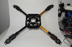
With the arms built and the speed controls soldered up, it was simply a matter of bolting the frame itself together. The HobbyKing frame is designed to fold, with nylon washers sliding on the fiberglass sheets. I don’t really need the folding feature, so I locked down the nylock nuts and they’ve stayed that way ever since. With the arms mounted, it was finally starting to look like a quadcopter.
Using the correct screws, the motors easily screwed into the frames. I did have to do a bit of filing on each motor plate to get the motor’s screw pattern to fit. The speed controls didn’t have a specific mount, so I attached them to the sides of the arms with double-sided tape and used some zip ties to ensure nothing moved. In hindsight I should have mounted them on the top of the arms, as I’m planning to put LED light strips on the outside of edges of the quad. The LEDs will help with orientation and ensure a few UFO sightings during night flights.
Power distribution is a major issue with multicopters. Somehow you have to get the main battery power out to four speed controls, a flight controller, a voltage regulator, and any accessories. There are PCBs for this, which have worked for me in the past. For the Hackaday Testbed, I decided to go with a wiring harness. The harness really turned out to be more trouble than it was worth. I had to strip down the wires at the solder joint to add connections for the voltage regulator. The entire harness was a bit longer than necessary. There is plenty of room for the excess wire between the main body plates of the quad, but all that copper is excess weight the ‘bench’ doesn’t need to be carrying. The setup does work though. If I need to shed a bit of weight, I’ll switch over to a PCB.
Click past the break to read the rest of the story.

The Electronic Speed Controls (ESCs) used in the Hackaday Test Bench contain linear regulators – trusty LM7805s to be specific. In an R/C situation, the 7805 supplies power to the receiver through the power wire of the three-wire servo lead The other two wires carry ground and PWM.
Connecting three linear regulators in parallel is generally a bad idea, but that’s exactly what the ESC designers have done, most likely to reduce costs. Since we have 4 ESC’s, connecting everything together would mean 12 parallel linear regulators split into four triplets, with several inches of wire between each triplet. That’s a recipe for disaster!
Linear regulators generally don’t play well together. One regulator will end up taking the load and either overheat or go into thermal shutdown. The extra heat does no good for the FETs running at 30 amps on the opposite side of the PCB. We’re going to get comments saying “but it worked for me”. But this is one of those things that will sort of work 60% of the time, then blow up without warning.
In many situations, the best course of action is to cut 3 of the four power leads, running the receiver and flight controller from the remaining ESC’s regulator. In this case however, we’re dealing with 4 cell LiPo batteries. Dropping the 16.8V batteries down to 5V at the currents we’re going to need would exceed the thermal limits of the regulators. The safe bet is to use an external regulator. I chose a switching dc to dc converter from Hobbyking. It wires directly into the main battery, and provides plenty of power.
At this point, things were down to the wire – literally. It was time to wire in the flight controller and receiver. The Hackaday Testbench is going to test several flight controllers, starting with the KK 2.1.5 multicopter board. It’s a good idea to isolate the flight controller from vibrations, so I used Kyosho Zeal gel mounting pads to stick it down to the top plate. The receiver stuck down next to it with standard double-sided foam tape. I’m using a Spektrum radio system for these early tests, though I’ll definitely be spending some time with the popular openTX software and radios.
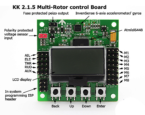
I connected the RX to the KK board using male to male servo connections. Everything followed the diagram. The BEC plugged into the battery input of the RX, which then sent power to the KK board through the servo leads. The ESC leads plugged into the M1-M4 connections of the KK board. With all the hard work done, it was finally time to power up the quad. Again, I kept the motors connected but no propellers installed.
The KK board came right up and informed me it was in safe mode. The button and LCD interface on KK board is actually pretty easy to use. I was able to enter the servo monitor and saw that my aileron, elevator, and rudder channels were reversed. A few quick transmitter setting changes corrected the issue.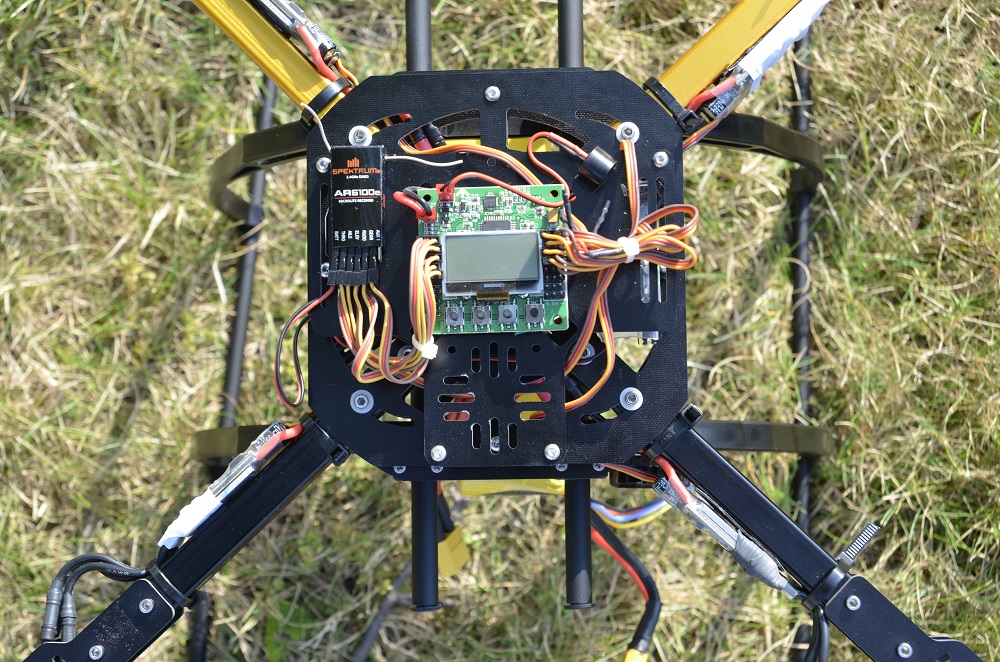
I configured the board for X mode and calibrated the ESCs using the KK boards pass-through mode. All the motors spun in the correct direction, and everything seemed ready to go. It was time to fly!
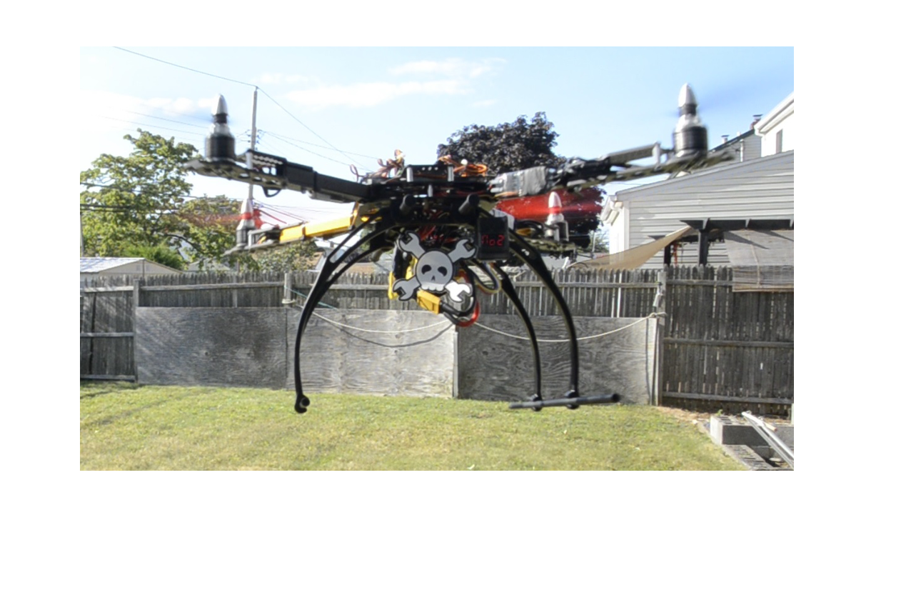
Maiden flight is a bit of a nerve-wracking affair for any aircraft. I kept the KKbaords PI values at their defaults for this flight, so I really had no idea if I was going to be faced with a slow to respond drunken quad, or an angry shaking bee. Outside I spun up the motors and got it light on its skids, just enough to verify the control inputs. Left stick made it lean left, and forward made it tip forward. Everything looked good so I advanced the throttle to hover. The Hackaday Testbed made its first lift off, and was actually very stable.
I hovered out the battery pack, switching the KK board in and out of self level. The PI values definitely aren’t optimal, as the quad feels a bit mushy. Still, it was a very successful first flight!


“The HobbyKing frame is designed to fold, with nylon washers sliding on the fiberglass sheets. I don’t really need the folding feature, so I locked down the nylock nuts and they’ve stayed that way ever since”
You may not need the folding feature for transport/storage, but it goes a long way towards adding resilience in a crash. See some of David’s videos on Flite Test for an explanation, as well as other relevant build tips (e.g., zip ties vs. permanent mounts for motors).
I agree with you on the folding helping in a crash – The nylon washers ensure the frame will still fold up if it takes a hit. Josh, Dave, and the entire Flite Test crew are awesome – they’re doing great things for the R/C hobby. I just wish Dave had stayed in the USA a bit longer. We need more tricopter guys :)
Indeed! loved his tri copter frame. Wish more companies would follow suit.
I so badly want to build one of these and later set it up for autonomous flight! I will be following this closely for while I’ve done some reading I’m nowhere near ready to purchase anything. Some RTF kits have raised my interest but I think something closer to open hardware type stuff is what I want. Appreciate this write-up and project!