
Welcome to part one of a series taking you down the rabbit hole of DIY electronic synthesizers based on (largely) CMOS logic chips. Instead of synths being commodity gear made by large corporate enterprises, we’ll be building with the cheapest available parts, using and misusing digital logic. In short, don’t expect pre-packaged smooth tones, because we’ll be making creative noise machines.
If you’re the chiptunes type, you’ll probably find something you like here. If you’re the circuit bender or electro-noise-punk type, this is gonna be right up your alley. If you just like to see CMOS chips wriggle and squirm in unintended ways, feel free to look over my shoulder. If you’re the type who insists that a screwdriver can’t be used to pry open a paint can, then maybe you’d better move along. There’s a thin line between the glitch as bug and the glitch as interesting discovery, and we’ll be dancing all over it.
To give you a taste of what we’re up to this session, here is a quick demo. Have a look and then we’ll get down to it.
It All Starts With Squares
 We’ll start off with one oscillator (yawn!) and then turn it into something much more interesting really quickly. Making this circuit playable takes a little more experimentation, but that’s the whole point. And along the way, we’ll be laying the groundwork for much more complicated circuits later on. We’re starting at the beginning, but the curve is steep.
Our simple oscillator circuit is based around a logic inverter. An inverter is a chip that outputs the opposite logical voltage level from what’s put in: if the input sees the high voltage level, it sets the output low (and vice-versa).
To see how to make a quick and dirty oscillator out of an inverter, think about what would happen if you connected an inverter’s output back into its input. If the input starts off low, the output goes high. But since they’re connected, the input is now pulled high which in turn sets the output to low, and we’re back where we started. This high-low-high-low feedback circuit gives us a basic oscillator, only there’s a couple more nuances we’ll need to look into.
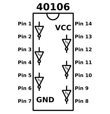 The chip we’ll be using for our oscillator is the CD40106BE; also called the HEF40106, depending on who makes it (datasheet, PDF) which is a hex inverter with hysteresis. It’s a great chip for our purposes because it’ll work on a wide voltage range so that we don’t have to stress about powering it. 5V is a good minimum, but 9V batteries are no problem and 12V is just peachy. Hex just means that there are six inverters in the same chip. You can see how they’re laid out below. Pin 1 is the input of the first inverter. Pin 2 is its output, and so on.
Hysteresis is just Greek for: state dependence. In our particular case, it means that the threshold value that the chip uses to determine whether the input is high or low depends on whether it’s currently high or low. The 40106 chip has two threshold values: a lower value that’s active when the input is already high and a higher value that’s used when the input is low. For the traditional use, this provides a degree of noise immunity; if the input is currently high, but fluctuating around a bit, it has to drop lower than the lower threshold to change state.
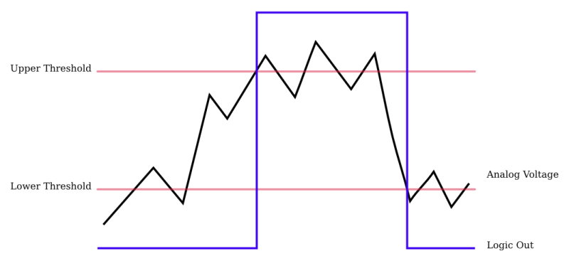
Here, we rely on hysteresis to make our oscillator run. If you substituted an inverter without hysteresis, its output would sit at the (single) voltage threshold. Why? When the output voltage gets a tiny bit above the threshold, it pulls the input up with it, and it switches the output low. When the output goes a tiny bit below the threshold, it switches back the other way. Instead of an oscillator, you end up with the chip thrashing back and forth internally just to hold a constant middle voltage level on the output.
If you add hysteresis into the mix, you get an oscillator. Instead of wiggling imperceptibly around one switching threshold, we have two thresholds. This means that the chip won’t switch its output low until the input rises at least up to the higher input level. Now, that happens pretty fast: when I build the circuit with straight feedback, I get a square wave that oscillates at 4.3 MHz, a few orders of magnitude too fast for human hearing. We need to slow the feedback down.
To lower the pitch down into the audio range, we run the feedback through a resistor to limit the current in the feedback path, and then charge up a capacitor with this current. The time it takes the capacitor to charge up from the lower threshold voltage to the upper depends on the current that it’s supplied. That means that the frequency is determined by the size of the resistor and the capacitor. A larger resistance limits the current, slowing the cycle down. A larger capacitor requires more charge in order to reach a given voltage, which also results in a slower cycle and thus lower pitch.
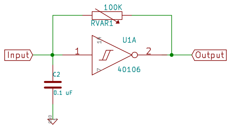
So look over the oscillator circuit for a second and we’ll recap. Imagine that the input voltage just crossed the lower threshold. Because the input voltage is low, the output is set high. The high output and low input causes current to flow through the resistor which slowly charges up the capacitor until the input voltage is higher than the high threshold, when the logic switches state and the output goes low. The low output then slowly discharges the capacitor until it drops below the low threshold and the cycle repeats. Tadaa! A square wave on the output bouncing between the two logic voltage levels.
But what about the input? Remember that the input sees the capacitor charging and discharging between the two threshold levels. Because the output voltage is constant and the voltage on the capacitor is increasing over time, the current that flows through the resistor drops a little during the cycle, so what we get is a “triangle” wave that’s made out of exponential curves rather than straight lines. (Good enough for gov’t work.) We’ll use this “triangle” waveform in a couple of weeks when we move on to linear-mode logic chip abuse, so just keep it in the back of your head for now. In the mean time, a scope trace is worth a thousand words.
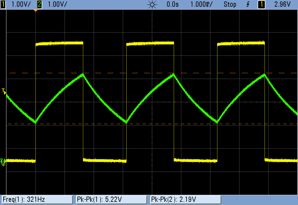
Here in yellow is the inverter’s output; a nice 5V square wave at 321 Hz. The green trace is the input, which shows the slowed-down charging and discharging of the capacitor. You can also see just exactly where the inverter’s lower and upper threshold values are, marked off by the dashed lines. As soon as the voltage on the capacitor reaches the relevant threshold voltage, the output switches state. And that’s the essence of the “relaxation oscillator” — it’s a simple feedback oscillator that takes advantage of the inverter’s hysteresis and is slowed down by charging up a capacitor.
And here’s what it sounds like. I used a potentiometer for the resistor, and I’m twisting the knob during the demo.
Build It
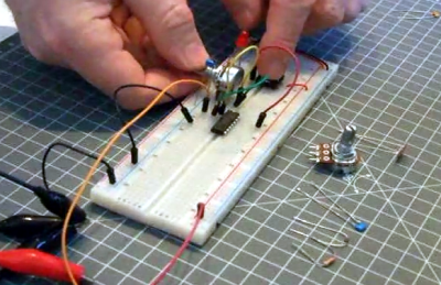
 Enough theory. It’s time for you to build yours.
To actually hear this thing, we’ll also need to connect it to an amplifier and speaker. I recommend the cheapest powered “computer” speakers you can find because they have built-in amplification with volume control and you won’t really care if you break them. I’ve even cut off the normal 1/4″ plug on the end of mine and soldered on alligator clips to make them easier to attach to breadboarded circuits.
If you’re going to connect DIY noisemakers up to something valuable, you’re going to want to reduce the output down to line levels: let’s say one volt peak-to-peak. If you’re running on a 9V battery, that means dividing down by a factor of nine-ish. You can do this with a simple voltage divider (see below).
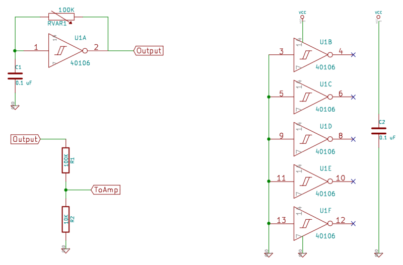
Finally, there’s two details that you almost always have to think about with CMOS chips. First, they make spikey demands on the power supply as the internal transistors are switching. To smooth this out, I usually add a 0.1 uF or 1 uF capacitor just across the chip’s power pins. Second, the unused inputs should ideally be connected to ground (or VCC, your choice). That means grounding pins 3, 5, 9 11, and 13. And don’t forget to hook up power to pins 7 and 14.
A practical circuit would look something like this:
Fire up your speakers / amp and give it a listen until you can’t take it anymore. For me that took about five seconds. (For my wife, about three.) Let’s see how quickly we can add a little pitch control and dynamics to make things more musical.
Pitch
First let’s work on changing the pitch up. The frequency is determined by how quickly the capacitor is filled up through the resistor, so we’ve got to change one or the other. Changing the capacitance is hard, so we’ll work on the resistor. Any way that you can put a variable resistance in this circuit is fair game. A potentiometer, as above, is pretty obvious.
A light-dependent-resistor photocell is a great option. You can then use light to control the pitch by waving your hands around, which is kinda cool. But it gets much cooler when you invite the LEDs over — anything that you’ve got that can turn on and off an LED can change the pitch of your oscillator. If you’ve been racking your brain about how you’re going to hook your Arduino up to this circuit: PWM to get different brightnesses and “control” the pitch.
And then there’s DIY resistors. Some old VHS tapes have a nice resistance that increases linearly across their length, but you may have to try a few before you find the right brand. (A really thick layer of graphite laid down by a dark pencil works just about as well.) Test the matte side of a bunch of tapes with an ohmmeter first before you go ripping them out of the cassettes. My copy of “12 Monkeys” has 37 KOhms per inch, which is pretty much ideal using a slightly smaller capacitor. I’ve taped the VHS tape down to a piece of cardboard and connected it to the circuit with alligator clips. I play it by tapping on the tape with another clip. Good vibrations!
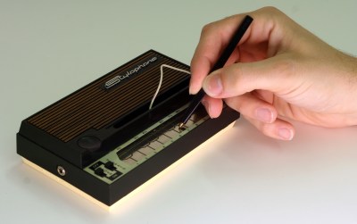
If you want multiple discrete notes, like a piano, you can connect a variety of resistors with one end connected in common to the capacitor. On the other end, connecting back to the output, you attach a wire that you use to select which resistor is in the circuit. See the stylophone for inspiration.
If your DIY resistor doesn’t have the same range as mine, or you just want to play different pitches, you can use whatever size capacitor you need to get the range you want, naturally. The chips don’t like to put out more than a couple of milliamps, so try to keep the minimum resistance above 2 KOhms if you want the chip to run in spec.
With the 0.1 uF capacitor that I’ve chosen 10K Ohms is a good lower limit for the resistance, otherwise the pitches get annoyingly high. Because of this, you might want to toss a 10K resistor in series with whatever variable resistance scheme you’re using. Otherwise, you’ll end up annoying the dog or disrupting bats’ flight paths.
Dynamics
If you’d just like to turn this thing on and off, we’ve got a few options. Easiest is to wire the VCC power supply through a pushbutton. Press the button, the chip gets juice and makes noise. Release, no power and silence. A quick way to improve on this circuit is to add a fairly large (10uF to 100uF) capacitor just after the switch. When you release the button, the capacitor will provide enough charge to run the circuit for a little while, smoothing out the release of the note.
Otherwise you can lean on the LDRs again, and make yourself a light-dependent volume control by adding an LDR to the voltage divider that I suggested above to get the signal down to line levels. Ping this LDR with an LED, and again you’ve got electronic control over the volume. We’ll do volume control more seriously in a few weeks, but for now you can cobble something together with an LDR if you really need one now.
If you’re building along, now is a good time to test some of this out on the breadboard, and maybe try to play a simple melody or whatever. At least try the button in the power supply trick, and try experimenting with different power-fade-out capacitor sizes. Once your familiar with one oscillator, we’ll throw in another.
Timbral Modulation
Now it starts to get interesting. (Oh, this is just the beginning!) We’ve got five inverter gates still unused, any of which could be used to add richness / modify the simple square wave we’re putting out so far. So let’s make an oscillator sync effect. If we build up another oscillator and use it to turn on and off our first oscillator and set things up just right, we’ll get the sometimes nasal, sometimes biting timbres of digital hard sync.
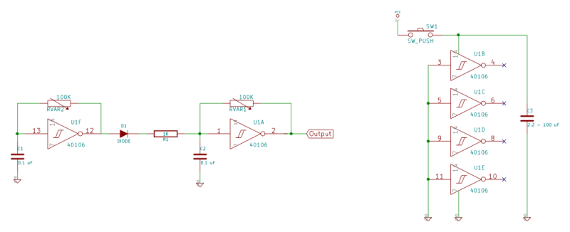
Build up a second oscillator just like the first, and connect the second’s output to the input of the first oscillator through a diode and an approximately 1 KOhm resistor. (The resistor limits the output current to keep the chip in spec.) When the second oscillator is high, it will conduct through the diode and keep the input on oscillator one always high, effectively turning it off. But when the second oscillator goes low, it will release oscillator one to do its normal thing.
The frequency of the first (fast) oscillator acts as a timbre modulator, and the second oscillator controls the overall perceived pitch. Let’s take it to the scope.
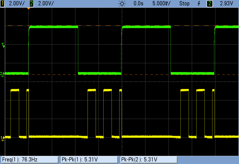
The green trace on top is the second oscillator, set to the frequency that determines the pitch. It’s a boring square wave. But the yellow trace on the bottom is the synced, higher frequency trace that we use as output. You can see that when the green oscillator goes high, it conducts through the diode and forces the input of the yellow oscillator high, and correspondingly its output low. When the green oscillator output goes low, the yellow oscillator is free to do its thing again; the diode only conducts one way. So we see the yellow oscillator start back up at its higher frequency until it gets cut off in mid-cycle by the green oscillator going high again.
This circuit sounds a lot more interesting than the initial boring old square waves, and it’s even more expressive when you can change the frequency of the synced oscillator. A potentiometer is OK, but here’s a great place to use an LDR to give you control over the timbre by waving your hand around over the photocell. The one caveat is that when the frequency of the synced oscillator approaches that of the syncing oscillator, you don’t get any sound anymore. So to play around, it makes a lot of sense to put the LDR in series with a potentiometer so that you can play with the range of the effect.
For extra credit, drive the synced oscillator’s frequency by pointing an LED at the LDR. Now however you control the LED will control the high-frequency component of the timbre. How close you get the LED to the LDR changes the depth of the effect, from subtle to really nuts. The pitch is still controlled with the potentiometer you’ve got running oscillator two, but the timbre is controlled by the LED. Of course, nothing stops you from applying the same trick to the pitch oscillator either.
Conclusion, and Next Week: Sequencers
So by now you’ve got something built up on your desk that’s either making completely autonomous noise with blinking LEDs, or you’ve built an expressive manual electronic instrument. If you get anything good, record it and link to it in the comments section. (And let us know how you did it.)
Next week we’ll add a sequencer to the basic relaxation oscillator framework here, so stay tuned. And if you’d like to pre-order yourself some parts, we’ll need a 4040 counter chip and (my favorite CMOS logic chip in the world?) a 4051 8-way analog switch. You’ll also want an assortment of resistors, probably an LDR or two, and a bunch of diodes on hand. And if you haven’t got those cheap powered computer speakers sorted out yet, get on it.
See you then.


cool, i remember a similar project for guitar effects pedals in the 1980s using a 74 series part that had some buffers and individual FETs
If you liked that, then I’ve got a bunch more similar tricks coming up for the installment after next. Stay tuned…
Yay, CMOS synthies … this somehow motivates me to pick up some stuff that’s lying around undocumented for much too long …
Oh, I forgot, I’ve got something for you to watch concerning the overall topic:
https://www.youtube.com/watch?v=NNrTlBXXwv0
The ICs you hear are:
4093 – wired as 4x pulse wave oscillators with gate input
74HC14 – wired as 6x pulse wave oscillator
74LS107 (JK-FlipFlop) – wired as 2x “octaver” (making heavy use of the asynchronous reset inputs)
I know the chips I use are slightly different than described above, but the circuits are practically equivalent.
Great droney instrument. Very musical, actually. Thanks a ton for posting that up.
I use 74HC14’s a lot in place of the 40106s, but it’s just so handy to be able to run stuff on a 9V battery that I decided to make this whole series 9V tolerant.
And if you like flip-flop octavers, check out the next installment. Binary counters (here, a 4040) make fantastic multi-octavers.
I’ll stay tuned for the next part of the series!
Unrelated: I’m sorry, I’m not trying to be a jerk, but I’m done reading hackaday.com through a browser until this layout is fixed. It’s atrocious. GIANT HEADLINE TEXT, followed by the tiniest snippet of content in a constrained layout just doesn’t work for me.
I’ll continue to read on Google+ and Twitter, but to me, this site is dead.
Try adding hackaday.com/blog/ to your bookmarks instead, that’s what I do – I agree, new home page sucks.
I did this, and told Firefox to forget hackaday.com forever. Now, when I start typing “hack”, it autocompletes to hackaday.com/blog.
Oh, that’s so much better! btw, your HTTPS config is borked, it is giving me wordpress’ cert.
I agree, the new layout sucks badly, but it can be corrected. Just grab the stylish extension for Firefox or Chrome then get the “hack-a-day old green” script from userstyles.org and edit it to get back the new colors and smaller headlines. It’s a 5 minute operation that males HAD readable again.
I could be snarky and say “could have used a 555″ but seriously- this is a great article, well documented and informative. I especially like the hard sync option right off the top, one of my favorite timbres. One very minor point – most computer speakers I have seen have a 3.5mm (1/8″) plug, not 1/4” as stated in article. Looking forward to the next one.
How many 555’s does it take to equal one Hex Inverter?!?! :)
Good catch on the plug size. I don’t know if you can see it in the videos, but for my benchtop computer speakers I cut off the plug and soldered on 3 alligator clips (left, right, and ground). Makes it super easy to attach to the breadboard. Just clip into the circuit wherever to give it a listen.
@williampowerlift f4f on insta
For everyone excited about this kind of projects: http://www.nicolascollins.com/handmade.htm
An excellent resource, Tom :) Glad you mentioned it.
I totally love Nicolas’ book. I have a first edition sitting around somewhere. His crazy experiments with contact microphones and thumpers (speakers driven to hit things) are fantastic.
CMOS noise FTW! While I’m slightly disappointed that you didn’t mention Stanley Lunetta, I’m glad to see this post. I built an open patch CMOS based noise synth with 36 modules. It is hands-down my favorite project ever. Here’s a quick preview-
[vimeo 100383138 w=500 h=284] lunetta demo 03 from chuck stephens on Vimeo.
And here’s a track recorded using it-
[vimeo 101062886 w=500 h=281] Confidence is High by nepchune from chuck stephens on Vimeo.
This track was recorded ‘live’. What you hear is the sound that came out of the synth with no editing.
Here’s a link to my Blinquencer- a 40106 blinking three LEDs on wire stalks to control two LDR controlled oscillators-
[vimeo 99430409 w=500 h=375] blinquencer optical semirandom sequencer from chuck stephens on Vimeo.
And here’s my Medusatron- Two FM 40106 based oscillators controlled by 8 LEDs sequenced with a 4017 decade counter-
[vimeo 59045912 w=500 h=375] The Medusatron Dual FM synth with Optical Sequencer from chuck stephens on Vimeo.
In the SDIY world synthesizers made with CMOS are called Lunettas. Google to find loads of information on the subject. Great fun, especially if you are into modular stuff and want to make weird noise instead of “serious” music where pitch accuracy and the like are desired. A couple of CMOS-based modules and some banana jacks will get you a looong way :D
I’ve lurked the Electro-Music forums for ages, and I was there when the Lunetta sub-section opened up. CMOS noise synths are certainly known as Lunettas there.
Anyone interested in this stuff should surely check them out: http://electro-music.com/forum/forum-160.html There are thousands of good ideas kicking around there, and I’ll be using a few in this series. I’ll cite my sources when we get into the innovative / attributable stuff.
I’m not going to stick to the Lunetta design in this column, though, so I went with something more generic. (I’m really fond of using CMOS chips for their analog quirks, for instance, which is Lunetta anathema.) But I’m definitely a huge fan. Good call!
http://s3.postimg.org/hikr0a7cj/elliot_noise.jpg
Oh yeah! I cooked up some CMOS synths couple of years back. It’s super fun and great way to annoy your spouse. I’ll dig my 40xx’s and 555’s from the closet once again.
What is with the auto download on the vimeo vid next to the bottom?
The dinner plate with 2 meatballs and croissant is ugly!
I will stick to ZynAddSubFX.
For all you coders and script kiddies out there check out bytebeat. It’s ‘music’ generated from a single line of code. I got into this recently using the droidbeat app and the output is very similar to what I get from complex CMOS patches. I’m not a programmer so I have no real idea what’s going on, but just inputting mathematical expressions produces some amazing, chaotic results, like a chiptune Lunetta.
http://countercomplex.blogspot.com/2011/10/algorithmic-symphonies-from-one-line-of.html
That is a great link-thanks :) Also, great job(s) on your noise modules. I am hoping to get started on a baby10 sequencer soon to drive a couple of things I have built. Nowhere near your level, but I enjoyed your posts.
Good call.
I actually ended up implementing these on the AVR as a code Easter Egg in the demos for Make: AVR Programming. In case anyone’s interested in running this on a microcontroller: https://github.com/hexagon5un/AVR-Programming/tree/master/Chapter13_Advanced-PWM-Tricks/arpeggiator (I think you’ll need to download the book’s libraries as well, also available from Github. Sorry about that.)
It’s super cool. Basically you’re using the inherent repetitions in bad random number generator (-like algorithms) to make audio. I never could get my head around how you’d systematically try to construct anything, though.
Next step is adding duty cycle control to the square wave: just one pot and two diodes needed, also different waveforms can be obtained by using the square wave to charge (sawtooth) or charge and discharge (triangle) a capacitor through a constant current. Sinewaves are a bit more tricky to obtain, by then you realize it’s better to start from sinewaves using specialized chips (ICL8038, XR2206 etc. all cheap on ebay). At this point you’re ready to move to the digital world where waves are contained in tables in memory and read by a master clock divided by some ratio which represent the played note.
Could you share am schematic to obtai other waveforms from this , will apreciate ir thankssss
Try here: https://hackaday.com/2015/03/09/logic-noise-sawing-away-with-analog-waveforms/
Love this article! :)
synths purely using logic (or mostly) are usually known as Lunetta synths
Great article.. My lunetta ‘blarp’ on vimeo
http://vimeo.com/19840807
Love that clangy metallic timbre! XORs?
I love his use of the capacitor to give it a release envelope. Hadn’t seen that trick yet in square wave synths.
I did an art piece with solar cells charging up a capacitor (BEAM-style) and then dumping into similar square-wavey synths. The way the frequency and volume both tail off, coupled with a trilling frequency modulation, sounded almost exactly like birds. So then I played up the whole solar/light/birds thing and littered them with LDRs as well.
The things you find out just by messing around…
I’m intrigued! Do you have a link where we could learn more about it? More details?
how should I place that capacitor? The envelope sounds great but I can´t figure it out from the video alone, I tried it between the switch and Vcc but no music gets through.
Thank you :)
If we’re talking about using the capacitor to keep the power running, then you put it across the VCC and GND, but downstream of the switch. You could connect a big cap up to the chip’s power pins, for instance. The idea is that with the battery turned off, the cap takes over and slowly drains by powering the circuit.
How long it lasts, and how much noise it makes will depend on the speakers/amplifier that you’re using though. If you’re driving into (e.g.) a set of amplified computer speakers, it can go for a long time.
I know this thread is old, but I couldn’t get that to work myself. Which pole goes to power? In one direction, it ended up more like an attack filter and the other direction did nothing.
Thanks!
https://www.youtube.com/watch?v=kuG__jFfwHQ
We use 555-based oscillation and pulse lengthening along with two new boards we designed: AND8 (8 AND gates, wherein one side is controlled by a 595 shift register and the other side is controlled by whatever signals you input), and MixMe8 (a passive summing mixer).
I like where this was going https://www.youtube.com/watch?v=2F9Y_RywjzI#t=669
11:40 starts the music
Enemies have a sentry gun covering a valuable position. This will save you from having
to re-install Diablo 2 should something go wrong. The highly skilled players help the newer players learn the game and develop their strategies.
I finally had the time to play with those 40106 a bit :) cool stuff, changed the capacitor to a higher value to get deeper sounds and need an amped speaker to continue. One should be around somewhere.
Where do you get 100K panel mount pots? I can’t find them anywhere ( granted, I may be searching wrong)
https://www.youtube.com/watch?v=VvnVJ76R4kY
What does it mean when he says “the second oscillator is high and CONDUCTS THROUGH THE DIODE.” Does that mean that current flows through the DIODE in the opposite way? Thanks! Anthony.
Hi Elliot, thanks for this great series. I’ve started diligently building these circuits and have run into a couple of weird problems which I simply cannot figure out. I hope it’s OK to ask for help. Here’s a picture of my breadboard: https://app.box.com/s/k1q66692btfhkobeau3dwg6aezgkuof5 . Shown is the “timbre modulation” setup, and the problem is: no audio — both oscillators work independently, but when I connect the output of OSC2 (pin 12) to the input of OSC1 (pin 1), nada (I get a click, and I hear some bleedthrough on my speaker, but no real sound). If I’ve read and understood, the circuit is correct. I’ve added a 100K resistor at the output to permit driving headphones, and to reduce the overall level on my amplified speakers, but have tested with that removed.
My second problem isn’t shown in the picture, but if I add a 22uF cap at the output of the switch (I’ve tried in-line to pin 14, and as shown in the circuit diagram), I get, in addition to a decay, pitch modulation. Which makes me think that something just ain’t right with my patching here.
Thanks in advance for your time + again for this series.
Having hit the same problems as you, I think the solutions are:
1. Adding a cap at the output of the switch doesn’t work as Eliot describes. Browning out CMOS is going to make it do weird things, and isn’t a substitute for a proper decay envelope.
2. I found the sync’d oscillators only work for narrow ranges of resistances. It was easier to select with a scope but you want the first oscillator to be at a low frequency and the second one to be high, otherwise the first will gate off the second entirely.
Complete NOOB here: What diode did you use, between output pin #12 and the 1K resistor, to input pin #1? Can you please provide a serial number or value. I’m trying t learn more about electronics and would love to build this circuit. Thank you kindly.
Excellent articles, even if I’m late to the party, thank you very much. I happen to have a bunch of 4049s (HEF4049BD) and MM74HCU04Ns from a grab bag. Would they work instead of the 40106, or is the hysteresis critical to operation?