
Making sound with digital logic usually calls for a Digital to Analog converter. Building one can be very simple, and the sound quality out of an R-2R Ladder is actually pretty good.
In the last edition of Logic Noise, we built up a (relatively) simple VCO — voltage-controlled oscillator — that had roughly one-volt-per-octave response. I even demonstrated it working mostly in tune with another synth’s keyboard. But what if you don’t have a control-voltage keyboard sitting around or you want to combine all of the logic-based circuits that we’ve been building with other circuits under voltage control? That’s where the digital to analog (DAC) voltage converter comes in.
R-2R DAC: Voltage dividers all the way down
In this session, we’re going to be putting together a simple DAC so that later on we can use our logic circuits to put out (analog) control voltages. When we’ve wanted a non-logic voltage in the past, we’ve reverted to connecting up a potentiometer to the two voltage rails and pulling off the intermediate voltage from the center pin, with the output voltage varying as we turn the knob. Maybe given that background, you won’t be surprised that we’ll be using a ton of resistors to build up a DAC that’s capable of making logic-selected intermediate voltage values.
In fact, a potentiometer with either end connected to VCC and GND, is a voltage divider. But they’re more general than that — take two resistors and put them in series. Now put a voltage across them. The voltage in the middle of the two depends on the values of the two resistors like so 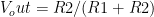
Say you want to divide a voltage in half? Connecting one side to ground and setting R1 = R2 does the trick nicely, and fits neatly with your intuition. If all of the voltage is dropped across two resistors, and they have equal values, you’d guess that half of the voltage is dropped across each one. Well, it is.
To build a DAC we want each input bit to produce a specific output voltage, and we then sum them up. In particular, if we want to encode the voltage as a binary representation, we just need to make sure that each stage of the ladder contributes half as much voltage to the final output as the stage before it.
That’s exactly what an R-2R DAC does. The R-2R ladder is made up of divide-by-two stages, so that when you apply a logic voltage (we’ll call the levels VCC and GND) to the top rung of the ladder, you get VCC/2 or GND. Add another rung to the ladder, and the top rung still produces VCC/2 or GND, and the rung below it produces VCC/4 and GND. Now the ladder can output four possible values: GND, VCC/4, VCC/2, and 3/4*VCC.
As we add more and more stages to the ladder, our highest voltage gets closer and closer to VCC and with each new stage the smallest voltage step is divided in half. For instance, with two bits we can represent the numbers 0, 1, 2, and 3, and the minimum voltage step is VCC / 2^2^, so the maximum voltage produced is 3/4*VCC. With eight bits, the minimum voltage step is VCC/256 and the maximum voltage is 255/256*VCC.
Thévenin Equivalent Circuits
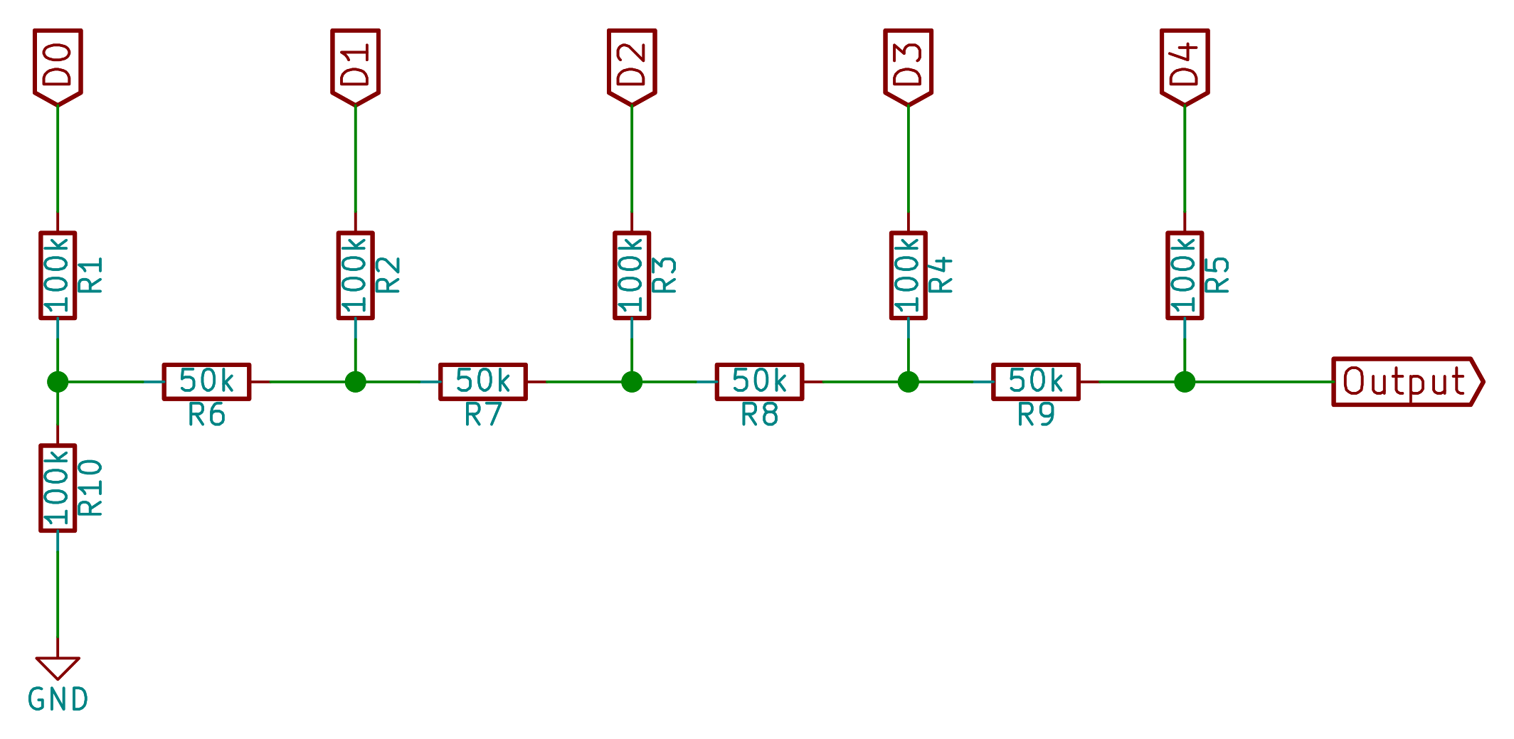
If you’re not content with my hand-waving explanation of the circuit above, you’ll need to know a little bit about Thévenin equivalence, but it’s not that bad. The basic logic is that any purely resistive circuit with a voltage source (like we’ve got here) can be treated as if it were just one resistor and a voltage source. And you can do this iteratively, so we can move up the ladder, collapsing everything below it into an equivalent voltage-source-plus-resistor.
In calculating the Thévenin equivalent resistance and voltage, you pretend that the input is shorted to ground and calculate the resistance. Viewed from the first junction (between resistors R1 and R10 in the circuit diagram), we’ve got two resistors of 100k in parallel, so the Thévenin equivalent resistance of the first stage is 50k ohms, and the voltage (V0) at the junction is VCC/2 if D0 is on, and GND if it’s off.
Moving up the next rung in the ladder, and doing the Thévenin trick again, we see that we’ve got two 50k resistors in a row (effectively 100k) in parallel with a 100k resistor again. So the equivalent resistance, treating V0 and D1 as if they were grounded, is 50k ohms again. When D0 is off, V0 is GND, and the output voltage is thus GND or VCC/2 depending on D1.
If, on the other hand, D0 is on, V0 is VCC/2. The resulting equivalent voltage when D1 is off is VCC/4 and when D1 is on is halfway between VCC and VCC/2, or 3/4*VCC, as we claimed above. Continue collapsing stages and writing down all the possible voltages, and you’ll get exactly the binary ladder that we discussed before. QED’ed.
And if you need to see it on YouTube to believe it, here’s a nice video explanation of how it works.
The proof of the pudding is in the tasting
And finally, if none of that’s good enough for you, and you share my empirical streak, build your own from the ground up and test each stage with a voltmeter. Or if you share my empirical streak but you’re lazy, just watch this video.
Implementation Details
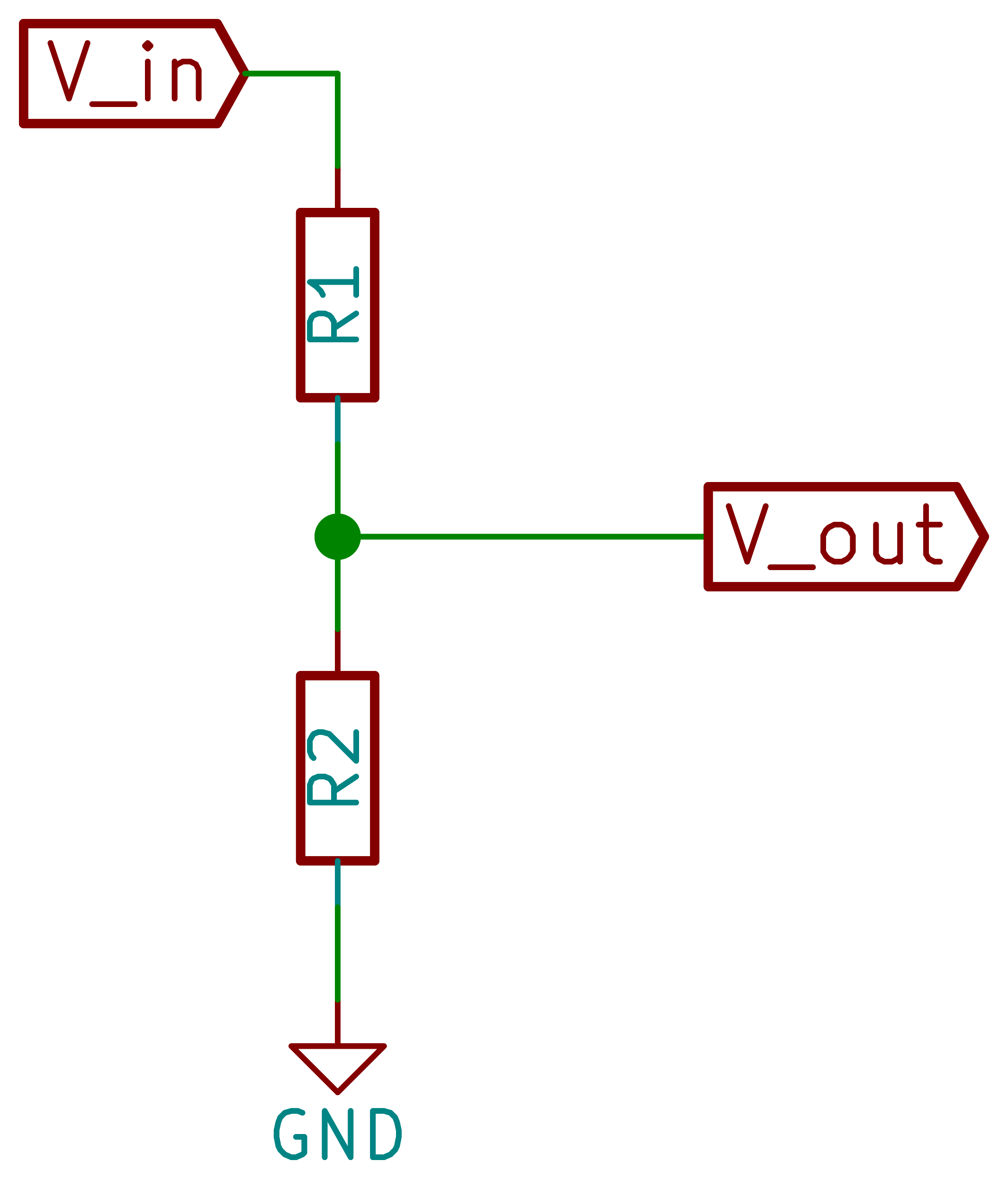
In principle you can build an R-2R DAC with as many steps as you’d like, but eventually you run into the accuracy of the parts themselves. An 8-bit DAC is just about within reach when using quality 1% tolerance resistors, but going much further doesn’t make much sense without buying higher-quality parts. For generating analog-ish waveforms, you can often get away with even fewer steps, and we’ll be using only five bits here.
We’ve not defined the values of R and 2R yet either, and there’s two different ways to go here, but since it’s hard to find resistors that are precisely factors of two from each other we’re going to make our own. Simply to make the circuit more compact on the breadboard, I’ve chosen R to be 50k, and 2R to be 100k ohms. But you don’t have any accurate 50k ohm resistors? Use two 100k ohm resistors in parallel. That way, you only need one resistor type to get the whole thing done.
Actually, there’s a side benefit to combining two resistors to get another value out: the two values essentially average out. If you’ve got one “100k” resistor that actually measures 101k and another that measures 99k, the series combination of them is exactly 200k, and the parallel combination exactly 50k. In short, as long as the values are right on average, using multiples like this can help.
And finally, note that any of these fixed resistors can be replaced with a potentiometer if you’d like. In particular, substituting a 100k pot for any of the 50k “resistors” gives you an interesting degree of adjustability in the output waveform, as we’ll see below. In principle, one could make a whole R-2R DAC with only potentiometers, dialing them carefully so that one side reads twice as much as the other. In practice, this works with three or four potentiometers, but it breaks down thereafter because potentiometers are usually specified for around 5% accuracy or less. Nonetheless, it’s a fun trick for producing odd, moderately tunable voltages from four binary inputs.
Buffering
But we’re not done yet. If you keep going with this Thévenin equivalent circuit logic until the last stage, you’d discover that it has (like each stage before it) an equivalent resistance of 50k ohms. That’s a lot, and it means that we can’t draw much current out of the DAC without the voltage sagging significantly. So we’ve got to buffer it up before we can use it directly, say to hand it off to your powered speakers.
And while you can totally use a transistor buffer circuit, we’d lose the roughly 0.6 volts needed for the base-emitter bias voltage. And heck, this is Logic Noise. So break out the 4069UB chip that we’ve been using for linear buffering duty since way early on.
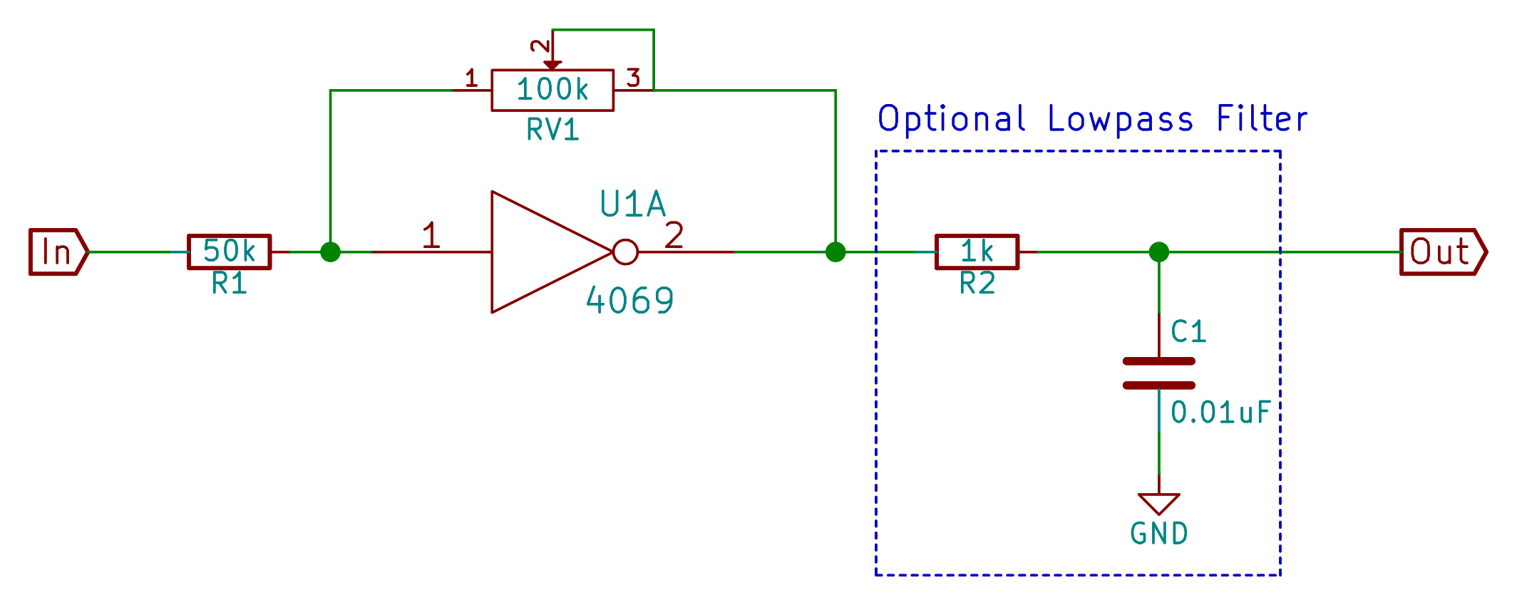
I’ve built up the buffer here with a potentiometer in the feedback loop so that you can vary the output level, and I’ve shown an optional lowpass filter on the output which tames some of the remaining digital character of the waveforms that we’re about to create. As always with the 4069 amplifier circuits, we can get a nice overdrive effect by amplifying the signal until it starts soft clipping.
The Digital Sawtooth
If our R-2R DAC gives us a voltage that’s increasing as we input increasingly large binary numbers, represented by logic high values on the input bits, we can use this to make an accurate sawtooth waveform. In an earlier Logic Noise we built a “sawtooth” waveform from our standard oscillator by adding a diode. But honestly, it was a fairly crappy sawtooth.
 Because what’s really going on in the circuit is an exponential decay of a capacitor, it was basically a sway-backed sawtooth. But now that we’re able to convert digital numbers into voltages fairly directly, we can make a very precise sawtooth wave, if that’s your sort of thing.
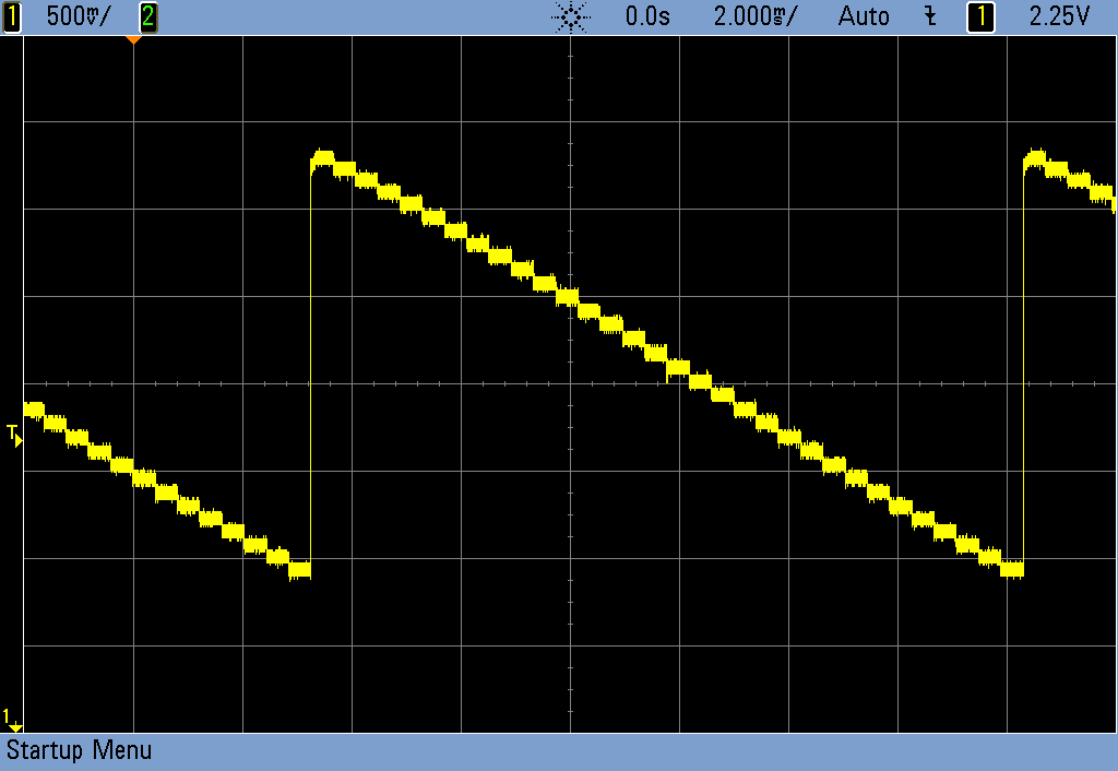 The secret is counting, and for that we’ll dig out a 4040 binary counter chip that we’ve used before. As a clock pulse enters the counter, its various outputs represent the number of pulses that have arrived so far. Put this binary number into our DAC and we get a simple rising voltage out. A up-ramp wave.
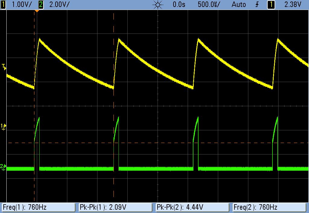
Now we feed the ramp into our inverting buffer circuit, and we get a beautiful sawtooth out the other side. If you want to filter it, you can. It knocks down some of the high frequency noise that comes from jumping between discrete voltage levels. It’s noticeable, so you should see which way you like it better.

The Digital Madness
There are two complementary ways of thinking of the above circuit. One is that we’re using a counter chip to count up in binary, and feeding this binary numeric value into a DAC. The other, more analog / musical viewpoint, is that we’re sending five square waves, each playing an octave apart from the next, into a voltage divider that reduces the volume of each by half. Stacking these up in the “right” order gives us a ramp waveform.
But switching the different square waves around as they enter the DAC gives us sounds with more high-frequency components in them. Right now, the lowest frequency square wave (the most significant bit) is the loudest. Swap the highest and lowest inputs, and you’ll see what I mean.
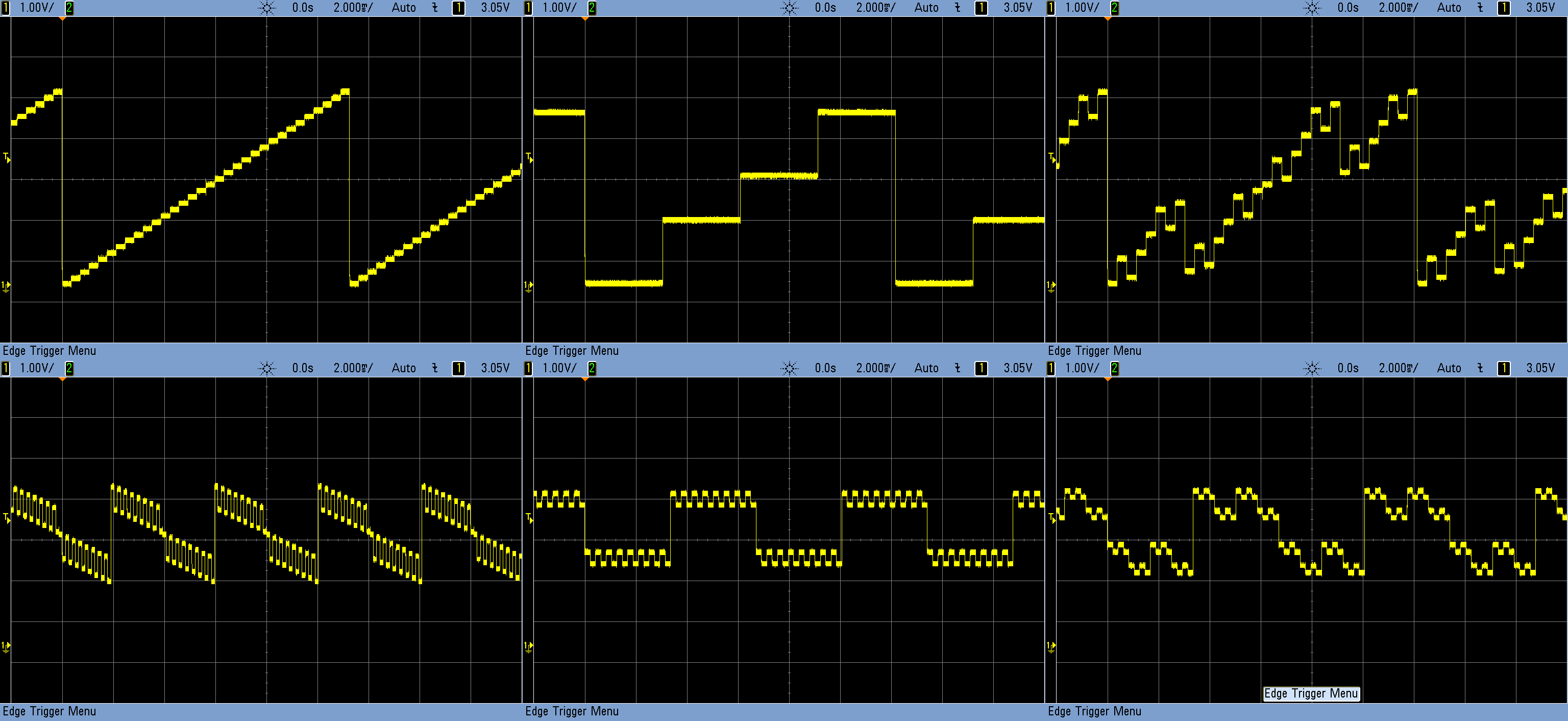
What’s fun about this realization is that you’ve got a way to (digitally) change the timbre of the output waveform by scrambling the inputs to the DAC around, or dropping particular DAC inputs altogether. And that’s finally the circuit you see demonstrated in the introduction. A 4066 switch (see Logic Noise: Ping Pong Stereo, halfway through the article) turns the four highest-pitch square wave inputs off and on, triggered by further subdivisions of the clock coming from the 4040 counter.
But there’s other ways to vary the timbre as well. With enough 4051 multiplexer chips, you could re-route multiple square waves to each of the DAC inputs. Or feed the outputs of our shift-register looper into the DAC. How you’re going to drive all of these is up to you.
Conclusion
If you’ve built up this session’s DAC circuit, don’t tear it up just yet. In the next edition we’ll be combining the DAC with the VCOs and tuning them all up. Tuning up circuits like this is tricky, and we may have to bend the only-logic-chip rules a little bit, but it’ll be worth it because I have a fantastic shift-register plus DAC plus VCO circuit to show you.


Addendum: The output impedance of an R-2R DAC is equal to R, regardless of number of bits.
Question: What is the output impedance of a “straight” log resistor DAC, as shown in this rad MSPaint schematic?
http://i.imgur.com/ruRFj4C.png
Tip: I think most designs follow the DAC with an opamp anyway, so output impedance is independent of whatever your generator circuit is doing.
If you hand pick the resistors, you can actually get by with el cheapo 5% or even worse. I used this approach when making my function generator https://hackaday.io/project/4129-function-generator. In the details section I link to a page describing how to do this, and what math needs to be done to keep things working accurately.
Thanks so much for this series! I built an open patch CMOS based Lunetta style synth last year and these posts have given me a wealth of improvements for the new and improved one I’m designing.
My very first DAC was optical. I ran voltage through a photoresistor mounted in the end of a light-fast tube. I arranged several LEDs run through trimmers as voltage dividers in the tube and fed them with logic signals. By adjusting the brightness of the LEDs with the trimmers, I was able to get a range of voltages through the photoresistor to drive my DIY vactrol based 40106 VCO. Super primitive, but sometimes the desire to do something is stronger than our understanding, so we find really dirty work-arounds. I still have two of those optical DACs in my Lunetta, and they’re perfect for noisy, out-of-tune ambient sound.
So you inspired me- I just finished a pair of new 6 bit DACs for my Lunetta. My old ones used 5% resistors, and though I used a meter to match them up, I didn’t have many to choose from so it wasn’t very precise. They were buffered through LM741 op-amps on a single supply. The new ones use 1% 22k resistors and I doubled them up for the half value, as suggested above. I buffered them through a LM358 dual op amp. I just mounted them in my rack and ran a patch and they sound awesome!
Now I need new VCOs…
Hey Elliot, just wanted to let you know I’m really enjoying your articles. Thanks!
Outstanding article. Thanks!
Holy crap!! I freaking love this series Elliot, you are awesome! I already have an R/2R ladder and a couple dividers sitting in my alligator clip modular.. and never thought to combine them in this way! I’m going to run down to the basement and try it immediately. Logic noise is the best!
Fantastic article absolutely loved it.
I’ve used quite effective r-2r ladders for VGA output from digital pins where the ladder impedience acts as a voltage divider to reduce the output from my fpga to more acceptable levels.
Just to note, how sure are you regarding the mixing of resisters says 100±1%KΩ to get 50±1%KΩ ?
Given a normal distribution of 100±1%KΩ you’re just as likely to get 101+101 giving 50.5 which is (50±1%).
Does this not mean that you are still having the same inaccuracy?? But admittedly steeper curves on your distribution?
Take the easiest case where 50% are +1% and 50% are -1%. If you combine two of these resistors, the worst case (as you point out) is still 1% off, but half of the time the positive and negative errors cancel out and you win.
That is, the four equally-likely pairings are: –, -+, +-, and ++. 1/4 of the time it’s low, 1/4 it’s high, and 1/2 of the time the errors cancel. So you’re strictly better off than without combining them.
(If you take more than two terms in your average, it gets even better, and this ends up being a fundamental observation in statistics: https://en.wikipedia.org/wiki/Law_of_large_numbers but we’re getting sidetracked…)
apropos of nothing, I am pleased that this article included – and correctly spelled – an explanation of Thévenin-equivalent analysis. It’s not a technique we tend to describe often for circuit hacking but it’s super-useful.
The equivalent resistance of 99K in parallel with 101K is not *exactly* 50K.
Parallel resistance formula: 1/R1 + 1/R2 = 1/Rt
If we define R as 100K, D (our delta) as 1K, R1 as R + D, and R2 as R – D, and Rt as R/2, the assertion is:
1/(R+D) + 1/(R-D) = 2/R
Putting the left side fractions over a common denominator yields:
2R/((R+D)(R-D)) = 2/R
Divide out the 2, and multiply out:
R/(R^2-D^2)=1/R, which is only true when D = 0.
I will grant that parallel resistance of R+D and R-D will converge to R/2 as D approaches 0.
Very confused here why ate you completcating natters with the delta?
1/(1/101+1/99)= 50
Nah, he’s right. 1 / (1/101 + 1/99) = 49.995 Close enough for Jazz. (Or 8 bits. Or 1% resistors.) But not exactly 50.000.
The super-right way to do it is to build up the 2R’s out of 2xR in series, but it didn’t fit as well on my breadboard. :) And practically, it makes no difference.
Thanks for taking the time to reply!
On both counts!
Sweet memories… We used these on 286 computers (among others to play mod files), connected to the printer port, for laptops of that era it was often the only way to output anything close to music. And the quality was partially better than what was commercially available then…
Yup… resistor ladder D-A for the parallel port of a Commodore computer, and load up the machine code file. “The Entertainer” was the ragtime piano tune that was the most popular. But the Commodore couldn’t do anything else at the same time but make the music.
See also: “Covox Speech Thing”.
Very nice read I had right here. Thank you Elliot, I really enjoy your writing!
maybe you could also do a bit on filters :) if you know how to. that would be awesome!
great to see a new article in this series, thankyou!
slight side track but reading about the method of combining square waves and dividing to make a sawtooth instantly reminded me of the korg poly800/ex800 which (somewhat cheekily) does what seems to be the exact same thing, been very well written up here: http://sequence15.blogspot.com.au/2013/08/how-korg-poly-800-dco-works.html
Hi,
Will the series be continued/expanded further, The amount of great info presented here has been very beneficial to my understanding and foray into DIY synths…I am really hoping there will be more.
Thanks again Elliot!
G
“In the next edition we’ll be…” – was there ever the next edition? Tried my best to find but no luck.
Oh man! I got painted into a corner with trying to keep things exclusively in logic chips, but wanting to do some more funky analog stuff that just simply requires an op-amp to do well.
But stay tuned! I’ve submitted a proposal to Hackaday Belgrade to give a Logic Noise talk.
What would you like to see in particular? I’m down for writing a few more installments…
I say go ahead and go where it takes you. You’ve covered a lot of ground regarding CMOS so you could branch away and bring in other concepts like opamps or whatever you think could complement the logic stuff. Maybe as a different series name? I dunno
I really want to learn to use op-amps my guy, do it. DO IT!
Since this series ended on such a cliffhanger with no continuation in sight, I tried to come up with follow-up ideas myself..
so here’s my take on how to use an MDAC for v/oct CV: https://www.youtube.com/watch?v=3v1yTFsypqA. (Hope it’s ok to share this here!)
Moritrz, I watched your videos and it is a good follow on to this series. Thanks for doing that. I enjoyed those a lot. Between these articles and your videos I have a good couple of weekends on my hands!
This site is Cmos fantastic!Please continue.