
In this session of Logic Noise, we’ll be playing around with the voltage-controlled oscillator from a 4046 phase-locked loop chip, and using it to make “musical” pitches. It’s a lot of bang for the buck, and sets us on the path toward much more interesting circuits in the future. So watch the intro video right after the break, and we’ll dig straight in.
4046 Phase-Locked Loop
The 4046 Phase-locked Loop (PLL) chip is a fantastic chip to experiment around with. In fact, it’s so versatile that we’ll spend the next three sessions exploring it. And still, we’ll only scratch the surface. Hackaday’s own Bil Herd is also in love with the 4046, and we’ve posted up tutorials on using it before. We won’t be using any of the intended functionality of the chips here, so check those links out when you’re done making bleepy-bloopy sounds.
PLL’s are sweet circuits. In normal use, you put in a waveform with a given frequency, and the PLL outputs a square wave that’s synced to the input, but at a higher frequency. It works by having a voltage-controlled oscillator (VCO) inside, and driving the VCO with a voltage signal that depends on the frequency difference between the internal VCO and the external signal. So far so good, by changing the voltage of the internal VCO depending on how out of sync it is, you can sync up the internal and external waveforms.
The trick to getting frequency multiplication is to divide-down the internal VCO’s output frequency, say by four, and then sync that divided-down result to the input. When the one-fourth speed VCO signal is synced up to the input, the straight VCO signal is running four times as fast as the input. Voilá, a frequency multiplier.
Simplest VCO
That’s all very clever, but for this session, we’ll just be using the built-in VCO. It’s a quick-and-dirty introduction into the world of voltage control, which has been what’s made the modern synthesizer work since at least the 1960’s.
To use the 4046’s VCO, we’ll only be using a few of its 16 pins. The VCO has an inhibit pin, pin 5, that we need to connect to ground, along with the usual VCC and GND pins. The voltage input for the VCO is on pin 9, and the output is on pin 4. And finally, the frequency range is controlled by selecting the capacitor on pins 6 and 7, as well as the frequency (and optionally offset) resistors on pins 11 and 12, respectively.
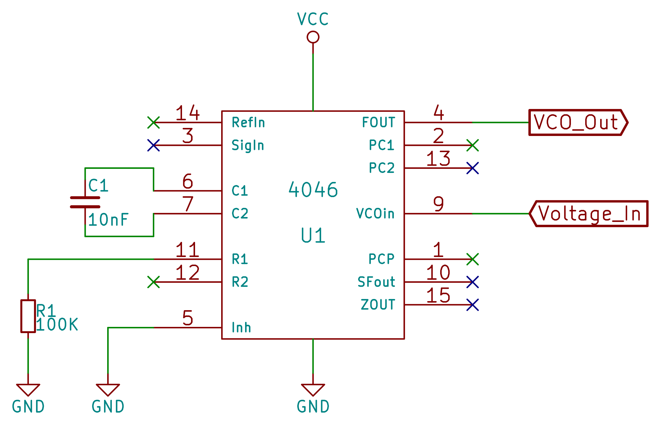 As you can see from the schematic here, it’s a no-brainer. A capacitor of 10nF and a frequency-selection resistor of 100K works just great. Since the product of these two controls the center frequency, you could also use a 100nF (0.1uF) cap and a 10K resistor. According to the datasheet, any value resistor between 10K and 1MOhm works just fine. You can also use a 100K pot here if you’d like to adjust the center frequency later.
There’s an extra (optional) complication with the offset resistor (R2). Adding a resistor to ground here shifts the whole frequency range upwards, which is nice if you’d like the minimum frequency to be something other than zero. The offset resistor has to be larger than the frequency-selection resistor above, but otherwise can be infinite. This would be a great place for a 1M or 10M potentiometer. We’re just skipping over it for now.
And that’s it. Two external parts, a resistor and a capacitor, and you’ve got a voltage-controlled square wave oscillator. Now all we need is a voltage source to control it. First up, a potentiometer hooked up as a voltage divider. One end to VCC and the other to GND, with the middle (wiper) terminal to the VCO’s voltage input. It’s just about the same functionality as the resistor-tuned oscillator from before, though.
Voltage Control
The fun in putting synth parts under voltage control is making up wacky sources of control voltage. Turning a knob with your fingers is great, but handing that duty over to some circuitry is better. And that, in a nutshell, is what brought the synthesizer out of the laboratory and gave birth to the modern synthesizer as musical instrument. In this video, we use an intermittent voltage source — a piece of VHS tape and a crocodile clip used as a voltage divider — to illustrate some of the things that you can do with a VCO that you can’t do with our resistor-controlled version.
You’ll notice that the voltage input is very sensitive. In fact, when it’s not connected to anything, it’s changing frequency wildly because it’s picking up power-line interference. We think the noise is great, but if you’re doing something musical, you’d have to tune up all your other instruments to the power-line frequency. In the video, we solve this problem two ways.
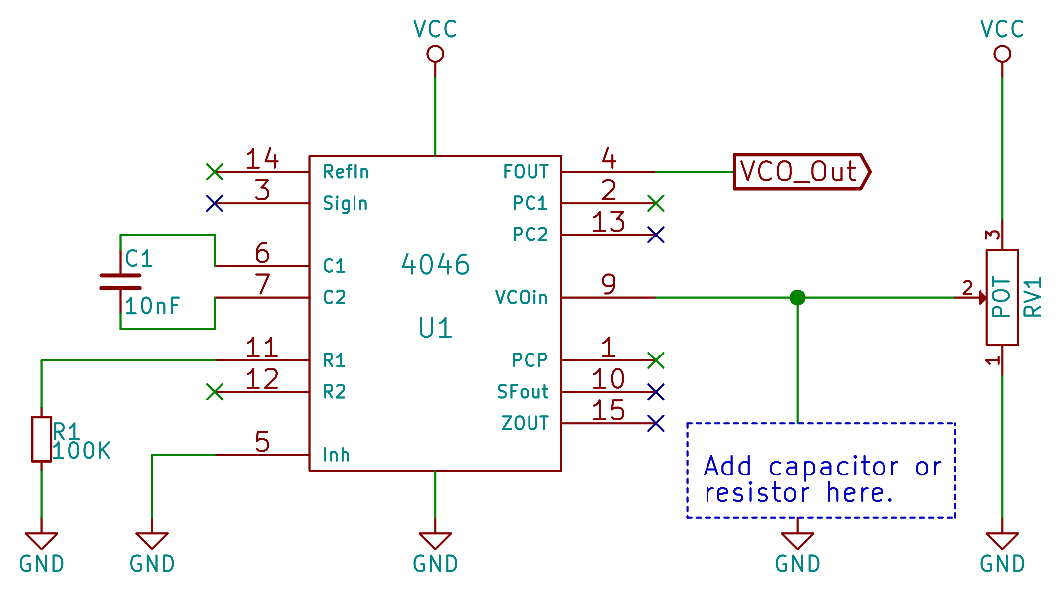 First, adding a capacitor to the voltage input of the VCO holds on to the last voltage for a while. This lets the last note continue to play even after removing our finger from the keys, or the croco clip from the VHS tape, as it were. Second, adding a resistor to ground, ideally one with fairly large value so that it doesn’t drag the control voltage level down, silences the VCO in-between actions. And mixing the two results in a pitch that slowly decays. (Whether that’s useful or not depends on you.)
Portamento, the sliding of pitch between notes, is also achievable with just a capacitor, although the speed will depend on the output impedance of whatever you’re using as your voltage source, so it’s not entirely reliable. There are better portamento circuits out there, but they’ll probably involve op-amps.
As a quick aside, you can make a rudimentary keyboard with just a bunch of push buttons and voltage sources. Indeed, a great device to have around is a set of buttons connected to an equal number of potentiometers that are configured as voltage dividers as we did in the first demo. Being able to tune each key independently makes up for not having very many available, and means you can play in whatever scale you’d like.
Voltage Controlled Sirens
Now let’s do something that we absolutely couldn’t do with a resistor as the control element: control the frequency of the 4046’s oscillator from another oscillator.
 To do that, we’ll build up an oscillator using our old friend the 40106. Use a nice large value capacitor (10uF is good) so that it’s got a nice slow swing to it. And instead of tapping the output, where there’s a full-range square wave, we’ll tap the input which has an analog triangle wave that bounces handily between the 40106’s hysteresis voltage thresholds.
 This is a simple and perfect combo. The 4046’s voltage input doesn’t draw much current at all, so we can connect it up unbuffered to the 40106’s triangle wave / input without changing the frequency. The triangle wave also doesn’t swing full-range, which is great since the 4046 will stop oscillating entirely below around 1.4V. And with one knob, you can create a slow siren-like effect or ramp the modulating triangle wave up to audio levels, and play around with crazy frequency-modulation (FM) type sounds.
Because continuous voltage sources get monotonous pretty quickly, we add a pushbutton at the end of the video. This also lets us show off the voltage-hold and voltage-decay tricks that we used before. Plus, adding a switch and a capacitor leads directly into sample and hold circuits, and that’s the topic of the next section.
Sample and Hold
 Sample and hold (S&H) is a fancy electronic engineer’s term for putting a capacitor and a switch into a circuit, but its a cool and useful effect to have in your synthesizer arsenal. Indeed, synthesizers going back at least to the original Moog modular had a S&H circuit on board. Why? It’s a cheap and cheerful source of almost-randomness.
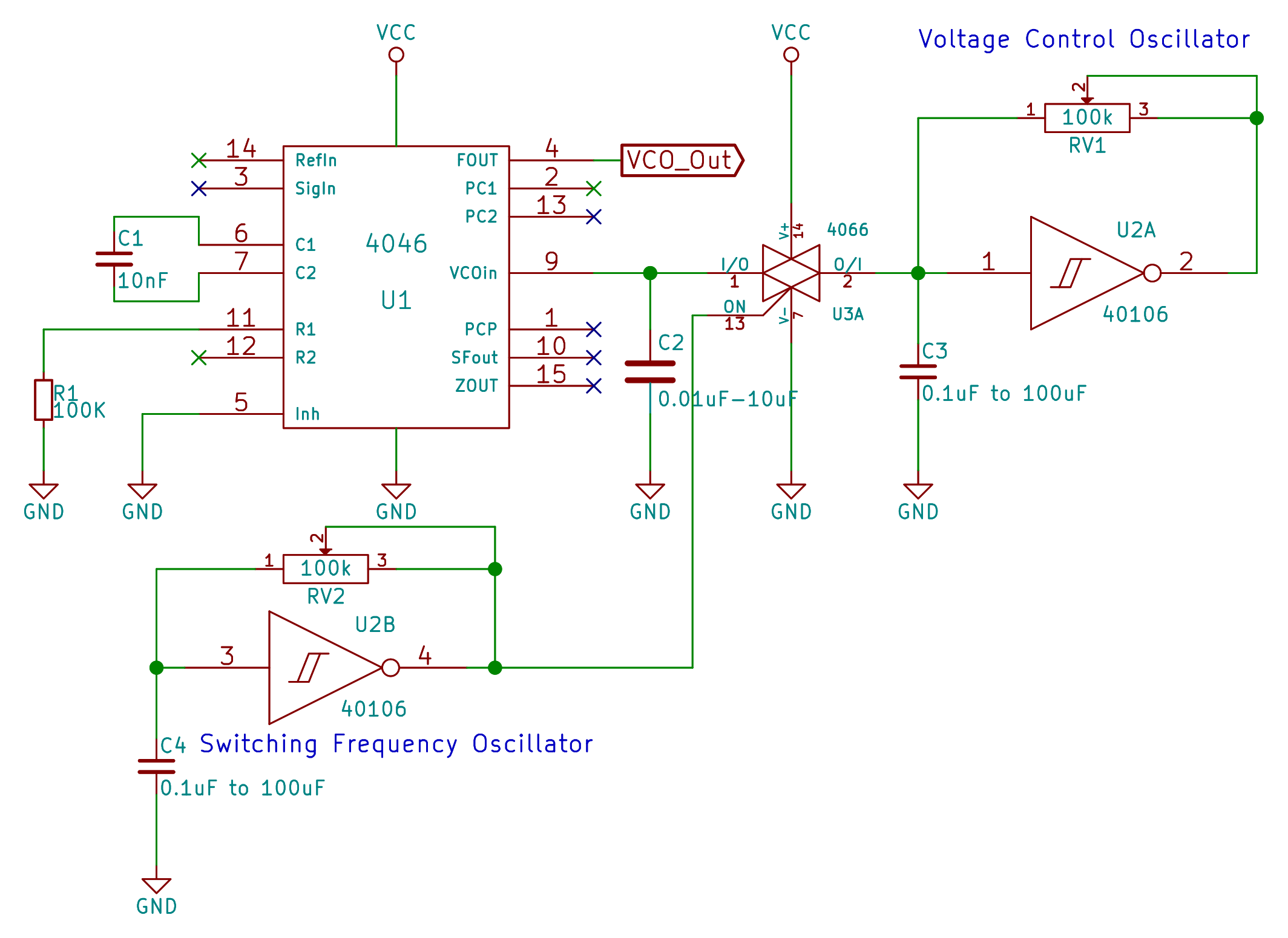
So we’ll hook up a second clock-rate oscillator on the 40106 chip, this time using the square wave output. Replacing our pushbutton with a 4066 digital switch puts the S&H under oscillator control. Capacitor C2 charges up to the oscillator when the 4066 switch closes, and holds when it’s open. For now, the time that the circuit samples (the button switch is closed) is the same as the amount of time that the circuit holds (switch is open). For now, we’ll stick to the basics.
There are actually three variants of the circuit here that are interesting. The first is the direct sample and hold circuit. When the sample and hold oscillator is high, and the switch is closed, the VCO tracks the pitch oscillator, and when the S&H oscillator goes low, the pitch holds at its previous level, just as when we were doing it by hand.
Another neat effect is to substitute a pulldown resistor (say, 100K again) for the S&H capacitor (C2). Now when the button isn’t pressed, the voltage gets pulled down and the VCO goes silent. This makes for a nice staccato sound that only plays 50% of the time, wherein the pitch tracks the pitch oscillator.
S&H Behavior

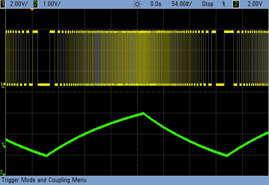
If you run the control voltage oscillator pretty fast (as in the first pane) and then sample it relatively slowly, it’s hard to predict what the sampled voltage is going to end up at. This is because the control voltage oscillator changes a lot over the sampling period. Sampling slowly from a quickly-varying clock source like this is a great trick to have.
If you do the opposite, sample frequently from a slowly-moving source voltage, you get this stair-step effect that traces out the general contour of the triangle wave, but holding discrete pitches along the way, as seen in the center pane above.
In the in-between zone, where both oscillators are running at comparable speeds, the sampling takes place at more or less similar places in the control wave. In the third pane above, you can just make out the capacitor moving with the control voltage when the switch is closed, but it all blends together. We’re really big fans of the region between total order and total chaos, so this is where we like to play.
In the real world, the S&H circuitry on things like analog-to-digital converters use very short sample pulses and tiny, low-leakage capacitors that charge up quickly so that it’s more like taking a snapshot of the voltage at a given instant. They also use special digital switches that turn on and off very rapidly and have extremely high impedance when they’re switched off. If you’d like to make something similar with our setup, you can convert the square wave into a pulse wave as we have done with the cymbal and drum circuits before. Play around with different capacitor values to lengthen or shorten the pulse length.
Next Session
We’re having a great time making pitched noises with our VCO. But we’re still not playing scales. To take the next step toward musicality, we’ll need to work on voltage scaling. It’s a lot easier to make music when a fixed voltage increment gives you a fixed scale step. Right now, that’s not the case, and we’ll get into the whole mess next time. It’s worth it.
But for now, enjoy the crazy voltage-controlled tunes / noises.


Wicked! I love this series a lot!
Great circuit! Going to see if I can interface as an extra oscillator for an MS-20xx.
The theory is, the MS-20XX would supply the exponential CV to the linear VCO on the 4046.
Time to breadboard
I’m really enjoying the series too. I’m wondering, in fact, if anyone’s going to put together a kit with PCBs and parts for all the circuits in the series so far – so you can have a really cheap, ‘hack modular synth’.
I’m curious, though, why use the 4046’s LDO instead of just making one with a comparator and a ramp generator?
https://hackaday.io/project/6540-logic-noise-klangorium
Awesome!
I would 100% buy one of those, but I just popped the gerber files into OSHPark and a minimum order of 3 was $150! I hope you manage to find a more cost-effective mass production way, otherwise I wouldn’t be able to afford it.
I did. I’ve got the board cost down around $5. Sourcing the rest of the parts (in particular the pots) cheap enough to make it a viable product / project is going to be tricky, but I’m going to (hopefully) get that done in early Sept.
It’s a damn big board, and if you’re paying by the square inch, that’s a problem. That said, I made it just about as small as possible while still retaining “playability”. If you squeeze stuff too tight together, it’s hard to plug/unplug wires unless you have tiny fingers or tweezers, and that’s not gonna fly either.
I wish I could say something smarter or more definite than “stay tuned”, but that’s what I’ve got at the moment.
I’d love to buy the bare PCB. I’ve been buying ICs to follow the series and most of the other parts I have (maybe not with the right footprint, but something can be hacked together)
Loved this HaD article.
Ooh, you’re going to add an exponent converter next. Nice, we all need our 1V/octave input :)
Hello, really great.
remembers me of the 1980s when i have made such things like a vocoder or a phaser out of cmos gates. The inspiration came from the german magazine ELRAD 12/1984.
SAme here, love it, keep up the good work!
Dude… this wins the internet! I can’t believe how useful this stuff is. Thanks SO MUCH for sharing and making everything so easy to understand. So great!! Just when I thought I was done adding stuff to my DIY modular…
Thank you very very much for this series!! It´s awesome!! How
How can I get the whole series?
Good question! :O
I dont know why, but i get nothing as output:( using CD4046BD, might that be a problem?
Same here, using cd4046be. Dont get it… Really great articles anyway, thanks a lot!
ALso can´t get it right with a 4046BE (2 of different brands). Thinking it´s the IC…
Um… my multimeter shows VHS tape as non conductive… what am I missing here. It obviously works great here, but when tested at home it failed. :(
It needs to be SVHS Super VHS tape, they are fairly hard to find unless you order online.
Hi, First of all thank you very much for all your work. Please I have a question wich concerne the process of PLL electronic experimentation with a breadboard. How do you do for to not have parasitic capacitance with this kind of components ? For me it’s really noisy and i can’t hope to test this circuit. Thanks for anwser !
i ve done this circuit in the past, im wondering if the 4066 could be replaced with one of the shmitt trigers from the 40106 (that has 4 more free oscilators?