Brushless DC motors, and their associated drive electronics, tend to be expensive and complicated. [Ottoragam] was looking for a cheaper alternative and built this Brushed DC motor servo controller and the results look pretty promising. Check out the video after the break.
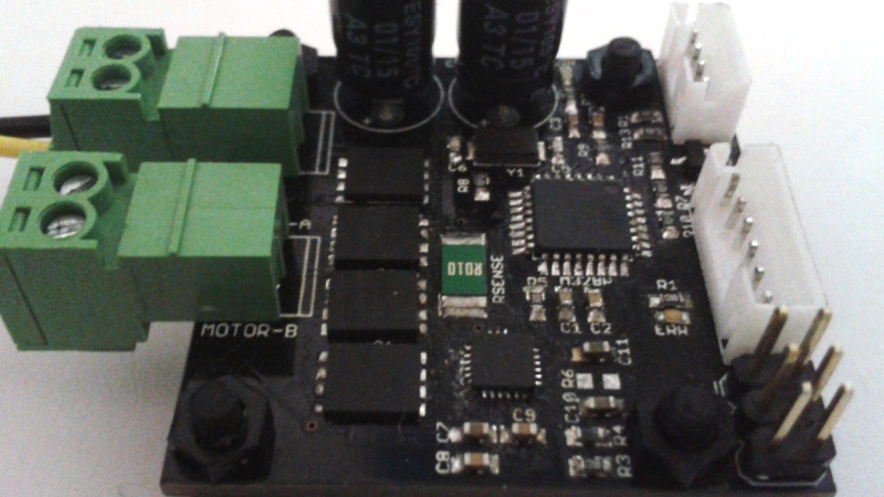
He needed a low cost, closed loop drive for his home-brew CNC. The servo drive is able to supply a brushed DC motor with up to 7 A continuous current at up to 36 V which works out to about 250 W or 1/3 HP. It does closed loop control with feedback from a quadrature encoder. The drive accepts simple STEP and DIRECTION signals making it easy to interface with micro controllers and use it as a replacement for stepper motors in positioning applications. All of the control is handled by an ATmega328P. It takes the input signals and encoder data, does PID control, and drives the motor via the DRV8701 full bridge MOSFET driver. There’s also some error detection for motor over-current and driver under-voltage. Four IRFH7545 MOSFETs in H-bridge configuration form the output power stage.
This is still work in progress, and [Ottoragam] has a few features pending in his wish list. The important ones include adding a serial interface to make it easy to adjust the PID parameters and creating a GUI to make the adjustment easier. The project is Open Source and all source files available at his Github repository. The board is mostly surface mount, but the passives are all 0805, so it ought to be easy to assemble. The QFN footprint for the micro controller could be the only tricky one. [Ottoragam] would love to have some beta testers for his boards, and maybe some helpful comments to improve his design.


This is excellent!
I have been thinking about this for cost-down CNC drivers. Brushed DC motors are much cheaper than steppers, they have higher torque and speed.
Originally I was thinking of geared reduction and a rotary encoder on the final (output) shaft but an encoder situated here needs to have a lot of resolution and that means expensive.
You could put a much lower resolution (and much cheaper) encoder on the motor shaft which sort of breaks some rules as the ‘play’ after the motor shaft is ignored by the sensing device. When you think of it, it’s the same for steppers anyway – the control metrics don’t include factors like ‘play’.
An even better cost down that may have some disadvantages is to AC couple the motor pulses back to the micro and count them. Very few additional parts and cheap parts in any case – some caps, resistors and op-amps or perhaps not even that.
+10 [Ottoragam] – excellent project!
play = backlash, does have compensation.
Thanks for your kind wods, RÖB, I’m really honored to have people that like my project. This is a work in progress, so expect more features to be added in the following weeks.
You do not want to have the encoder on the final shaft if there is any sort of backlash. It is a nightmare to tune. You have to use very soft PID settings to stop it from oscillating which will limit the performance significantly. You can do a second encoder loop on the final axis and use that to ensure final positioning accuracy. The kflop can do that and it is an option on commercial cnc mills.
yes +1 for two encoders…
Machdrives also does a low cost dual encoder servo drive for brushed DC motors.
http://elm-chan.org/works/smc/report_e.html
has UART for setting parameters even
I do plan to implement serial communications between the driver and the PC for setting parameters and even for running an algorithm for autotuning the PID loop on the PC. Also, my servo drive accepts STEP/DIR signals, so it can work where a stepper motor was being previously used ;)
How about one able to handle 1 or 1.5 horsepower, 90, 100 volt or higher treadmill motors?
Probably better off going for a commercial product for those levels.
Phase angle controllers work nicely for universal motors.
I did a coil winder about 20 years ago using a dc servo drive and quadrature encoder setup, controlled by a Z80. The software locked up, it didn’t see the end stop micro switch and broke a support bracket. In the next version I added two micro switches just off themechanicl end stops, both in series with the motor, and with high-current diodes across them, so that if the software crashed, the open micro switches would disconnect the motor, but the diodes would allow the drive circuit to back the motor off the end stops.
Good job! How many lines is the encoder you are using? Are you running the A and B phases to interrupt pins or are you using deditcatd hardware counters (like IC1A/B) on the avr? I did this a few years ago in an fpga (pid control in hardware too) with a 100,000 line encoder and it turned out to be quite a challenge. If I were to do it over again I would use a micro with a dedicated quaderature decoder like the stm32.
Thanks Lou! I’m using a 1024 cpr encoder (with 4x decoding) that gives me about 5 micrometer resolution on a 5mm ballscrew for my CNC machine. I connected the A/B channels to the pair of external interrupt pins of the AVR, so I’m not using the Input Capture feature of the AVR, (there was a good reason for this, but I’ve forgotten what it was): The encoder I’m currently using, the AS5040, can output the decoded quadrature signal too, but I decided to program a quadrature decoding state machine in the uC to allow for maximum encoder compatibility. I’m thinking of writing an alternative firmware to allow decoded quadrature as input for the driver, to speed things up.
And when I update the microcontroller on this project I’ll surely go for a part with dedicated logic for the decoding. The PSOC4s were suggested to me by another Hackaday.io member.
consider the stm32F4xx series. with quadrature support in the hardware timers that aspect would become simple.
The arduino Due has a quadrature decoder block as well. Speaking from experience, DO use a hardware block/dedicated IC for this filtering and decoding, that will save a lot of work and risks of processor lock-up due to high interrupt frequencies (especially with these 1000 lines encoders)
The VESC open source motor controller for robotics and skateboards can also be used for CNC. It handles brushed DC motors and brushless motors in FOC mode, with sensors (hall, quadrature encoders). 50 Amp continuous, 240 Amp peak, at 8 to 60 Volt, uart, canbus etc. See
http://vedder.se/2015/01/vesc-open-source-esc
Yes, YES! I’ve done this myself and find the concept to have some superior features to steppers. Glad to see another article featuring closed-loop dc motor control. A year or so back, HaD did an article on this where I guy had adapted it to a 3d printer. http://hackaday.com/2015/01/20/closed-loop-control-for-3d-printers/ And in fact this article inspired me to embark on my own CNC machine-building journey which has been quite successful and exciting. The aforementioned used ServoStrap which was a PID controller. I’ve adapted that to my own circumstances. The result of these controllers use step and dir signals just like a stepper controller so it’s compatible with GRBL and any controller that does STEP/DIR.
Many thanks Anool and Hackaday for giving this project some blog time! It was incredibly awesome to wake up and discover that a lot of new people were now following the servo drive.
Any questions/suggestions are welcome.
I suggest a “how to build one” manual, hehe.
I have been wanting to dip my toe into this for my own use but it has been extremely difficult to find anything that someone with my skill set can use. If I knew how to engineer a driver board myself, then I would. But alas, my abilities are limited to building a board of someone else’s design and pasting code (and maybe minor edits) to program a chip. Even better for others who don’t have the ability to make their own board would be to be able to purchase the PCB and download the code.
I have seen several examples of home-brewed driver boards folks have got to work, along with video similar to yours showing it in action. And congrats for that because that is extremely cool. And I don’t know how to not sound selfish and stupid (maybe because I am and I am I guess) when I say PLEASE take it to a level, soon, where folks like me can click on a web page or eBay or the like and purchase a board and code from you so we can join in on the fun !!
I’m not sure the “mail a beer to Denmark” business model has proven to be all that helpful or convenient (i.e. UHU if you’re familiar)
Anyway, congratulations on your success. It looks like a slick execution. I like it. I want one!!
It’s really awesome that you like my project. If there was a though hole or big SMD version of this, would you be comfortable assembling it? If so, stay tuned for more :)
“would you be comfortable assembling it?”
Sure would, whether through hole or big SMD. I’d be smiling the whole way too. You can bet I’ll “stay tuned”.
I second the idea! I like through hole myself :) I am using dc motors with a planetary gear housing to work the limbs of an arm. I’m in early stages right now and your work looks really promising :)
That is one of the applications I had in mind when creating this this. I’ll see what I can do in terms of making this more accesible in terms of assembly to the majority of people, and of course, your suggestions are welcome.
Runaway motor detection and shut down? Nothing worse than having an encoder or cable break and have the servo take off and slam against a hard stop.
Good to have you here, macona, your input is always top notch. I didn’t think of that, and it is risky to operate without detecting that kind of fault. I’ll try to patch it asap.
Been thinking about this too. I’m glad smarter people than I have been working on it.
This is SO cool. I have been working on similar project. I wanted to design a controller which can be used to convert any normal low cost DC motor into servo but having limited rotation of 180 degrees like hobby servo. I have tested normal low cost DC motor with potentiometer as feedback sensor for this setup but these motors have very high backlash problem. Finally I took one of my servo motor and used it in the setup. I have developed a GUI based on Matlab. I can monitor things like ERROR, POSITION, PID Output and can change online things like Kp,Ki,Kd, Dead band,Integral operation range. I would like to develope a GUI for you system.
Hi, Saurabh, any help is welcome. Shoot me a personal message so we can discuss the GUI aspects.
Actually I cant find here how to message you. This is the first time I am making comment on Hackaday. So guide me about how to do that
You can reach me trhough my Hackaday.io profile https://hackaday.io/ottoragam, or mail me at ottoragam at gmail.com :)
I have worked on similar project. But there are some differences. I use potentiometer as feedback sensor(hence limited rotation). I used arduino for controlling. I made a GUI on Matlab where I can observe the response of motor. Quantities like Error, Current position,PID output can be monitored on GUI. along with this I GUI can be used to set almost all the PID parameters. GUI also have option to provide new set point to the controller so that its possible to observe system feedback and tune according it.
Best article I have been working on similar project. I wanted to design a controller which can be used to convert any normal low cost DC motor.I can fetch some information related to our new informative piece of content on d.c.drives .
Amazing project! I’m planning to build something similar to that, to control X and Y axis in a CNC machine, as I already have some really powerful car wiper motors (I’m afraid the wormgear has a lot of backslash, but I’ll remove it and use direct coupling between the motor shaft and a leadscrew). I’ve tried to build an “software servo” using LinuxCNC, counting the steps via parallel port and using pid to control the motor without any extra hardware, but even though it sounds cool, the transfer speed of paraport is very limited, thus I got way too much lost steps when using higher speeds on the motor.
I’d like to know how many steps can you realiably count per second with your driver? I’m asking this because a project that appeared here on HD last year (on https://github.com/misan/dcservo), and I’m particularly interested about using ESP8266 instead of ATmega328P along with a dedicated H-Bridge, because having a higher clock allows to count more steps per second, right? But as you use a dedicated decoder, I really don’t know wich one will be better, what do you think?
(Sorry for my poor english haha)
ive been working on a new servo actuator, and i stumbled on this page, right now the roadblock is programming the microcontroller, ive managed to get a schematic together for the pcb. Could you please let me in on how do we go about programming the microcontroller. im looking at using an ARM cortex m3 for my pcb
I am in the process of cocieving a brushed DC drive for CNC.
I found an encoder by CU I that uses the same capacitive technology as dial calipers. It does the counting and replies with absolute position in high speed serial form.
I haven’t bought one yet but on paper it seems to be a real problem solver.
https://www.cui.com/amt-faq
John
John
DC servo drive control operation, it is really possible to learn from it, let yourself practice.