Wafer level chips are cheap and very tiny, but as [Kevin Darrah] shows, vulnerable to bright light without the protective plastic casings standard on other chip packages.
We covered a similar phenomenon when the Raspberry Pi 2 came out. A user was taking photos of his Pi to document a project. Whenever his camera flash went off, it would reset the board.
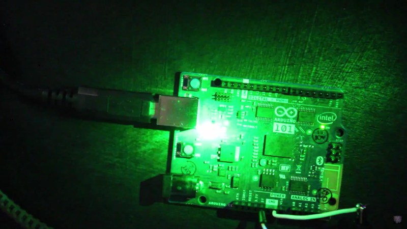
[Kevin] got a new Arduino 101 board into his lab. The board has a processor from Intel, an accelerometer, and Bluetooth Low Energy out of the box while staying within the same relative price bracket as the Atmel versions. He was admiring the board, when he noticed that one of the components glittered under the light. Curious, he pulled open the schematic for the board, and found that it was the chip that switched power between the barrel jack and the USB. Not only that, it was a wafer level package.
So, he got out his camera and a laser. Sure enough, both would cause the power to drop off for as long as the package was exposed to the strong light. The Raspberry Pi foundation later wrote about this phenomenon in more detail. They say it won’t affect normal use, but if you’re going to expose your device to high energy light, simply put it inside a case or cover the chip with tape, Sugru, or a non-conductive paint to shield it.
EDIT: [Kevin] also tested it under the sun and found conditions in which it would reset. Videos after the break.


It’s not a bug, it’s a light sensor.
Exactly!
Hook a relay up to the boards LED pin, from there power some LED light strips through the relay. The last step is to place the board in a situation where it’s exposed to light when the sun rises.
Congrats you have automated lightning without an ounce of code
Just add “Built in Light Sensor” to the features list!
That was also my first thought.
Not to great, opened case alert. :D
So^^^
Opto-Isolated Reset Circuit.
All Field Effect Transistors are sensitive to carriers (electrons or holes) appearing in their channel. YEARs ago I designed chip testers at IBM. One could display the fail pattern (“Fail Map”) immediately after a test, and then log it. Engineers would carefully align probe sets on a wafer to test a particular chip, using a ring light attached to the microscope. We were used to seeing a pattern of probe fingers on a fail map when the Engineer forgot to turn the ring light off!
Ha! That’s like telling a Dr. it hurts everywhere you touch yourself and the Dr. replies “Your finger is broken.”. Leave the light on while testing wafers and fails everywhere it’s tested.
This looks like the same disasterzone fault with some of the later model RPis we saw that would reboot because of camera flashes against the transparent regulators.
I wonder at what point people will begin to work in flashbulb tests against their finished products, or if this is generally seen as too much of an amateur mistake to test for?
Or just stop using uncapped silicon parts in their finished products. I understand using it in a cellphone because 99.9% of the time unless it’s being recycled that cellphone is never leaving its case.
Where as things like the Pi and the Arduino will very possibly, in fact very probably operate without any sort of case. Which exposes a potentially photosensitive component to the very thing it is sensitive to.
Chipscale packages can be used when exposed to light, mostly. Camera flash bulbs and lasers directly to the package are extremely bright sources. Even some packaged ICs can be influenced by a high power laser as the plastic is very thin.
The sad part is that the vendors don’t usually offer packaging alternatives to these parts other than chip scale. I looked at a TI part series and their chip scale part is better than the conventional one (different part#).
Small dab of paint or epoxy blob will fix it and is easily added to the assembly process. It’s even a part of all electronics assembly systems as it’s a common thing to do.
Bright light does not in any way affect the Raspberry PI not arduino. Problem is electrical discharge which happens in xenon flash tube. Plastic that all the chips are in is opaque enough that the photo effect does not occur.
To test if this devices are photo sensitive try to flicker laser pointer over it when functioning. You’ll probably find out that nothing happens.
While I can’t say how it would affect the chip, but all light is a form of electrical discharge. It just so happens to be at a frequency we can see.
Your terminology is incorrect. Photons are not “a form of electrical discharge.” An electrical discharge is the flow of electric charge (either as electrons or other charged particles) through matter. Photons have no electric charge and are not affected by electric fields.
You were probably confused by the energy conversion via the photoelectric effect. Whenever an electron (which may be part of an electrical discharge) changes state, it emits a photon; the reverse is also true (Photons can change the energy state of electrons.) At low energy levels, the photons have wavelengths in the radio range of the spectrum. As the magnitude of the change in electron energy state increases, the wavelength decreases (as described by the Planck equation). If enough energy is released, the photon may be in the visible portion of the EM spectrum, or even up in the UV or X-ray range.
Since BJTs and FETs both rely on electrical charges to operate, the high-energy photons from a flash tube (which may include higher-energy UV as well) change electron energy states, causing them to move through the device, changing the flow of charge through the circuit.
Oh, here we go…
It’s just a semantic difference – thinking of things as discrete “particles” which interact really causes a ton of confusion. Photons are quantized wave solutions of the electromagnetic field – if you have a spark, for instance, the resulting “sudden” change in the electromagnetic field causes an impulse to propagate outward. That impulse can be thought of as a superposition of photons of a very broad band of frequencies, but well, you can also just think of it as a “spike” in the electromagnetic field.
If you have a broadband antenna, for instance, and you point it at a spark and record data when it goes off, it looks like a spike, just a sudden jump in the voltage at a point. (You, too, can do this, with a ‘scope, an antenna, and one of those piezo cigarette lighters).
But that spike is actually *more* than just a bunch of photons shoved together. When you’re far away, you only see the *propagating* portion of the field, which are the wave solutions. When you’re *near* the source, you can also see the field portions which die off fast – that’s the ‘near field’ coupling. And in those cases, you don’t actually have ‘photons,’ you just have ‘an electric field.’
So, you’re partially right that photons are not a ‘form of electrical discharge.’ Photons are always generated in any electrical discharge, because, well… they *are* the electrical discharge. But photons are really just a wave solution to the electromagnetic field.
“Photons have no electric charge and are not affected by electric fields.”
While this is true, it’s not really terribly useful to think of it that way. Photons *interact* with everything that has an electric field of its own (… because they *are* the electric field). They just don’t self-interact, because, well, that would be bad.
(If you want to get even more semantically silly, photons are actually *defined* as the portion of the electroweak field that *doesn’t* self-interact, so saying ‘photons don’t interact with an electric field’ is like saying ‘2+2 = 2+2’. That’s true by construction).
https://www.raspberrypi.org/blog/xenon-death-flash-a-free-physics-lesson/ “More good news: the effect only happens under VERY specific circumstances. Flashes of high-intensity, long-wave light – so laser pointers or xenon flashes in cameras”
You couldn’t even bother to read the summary?
That is exactly what he did.He used a laserpointer… and found the light sensitive effect
Not sure why they don’t either use a different part or design the board with enough room around the component to put a protective black blob over the photosensitive component.
I wonder how much capacitance would be needed on the 5V so the Arduino could survive a camera flash. Though I suppose it’s possible that the wafer chip shorts the 5V supply which would quickly drain the caps.
He measured the drop as 5ms. That’s a long time in electronics-terms. At the maximum USB current of 500mA that would come to C = I . dt/dU = 1250uF. That’s a significant capacitor.
In the ‘pi there was a “high impedance” analog node in the circuit that would change state significantly from the few electrons injected or leaked by the flash. Something similar is probably going on here. A node in the circuit in the chip is being charged or discharged by the flash causing the output fet to behave contrary to specifications.
Or just use a late model android phone to take even closeup pics of anything with good normal lighting. I always hated flash even back to when I was held in mother’s arms in a group take. Now we don’t need it at all.
Would indirect flash affect it? I usually bounce flash with an external dslr flash. Improves the light a great deal too, much softer and pleasing to the eye and no direct flash hotspots on the subject.
Might help, might not, depends on the threshold, how much brightness is required to trigger the component in question. Android phones use a white LED, I’d guess the “flash” is longer, energy more spread out in time.
Still, bit of black paint, the solution’s already been said!
Intel Edison has some chip-exposed parts as well, right? has anybody ever tested it for light exposure related failures?
Why would you want to take a picture of the Arduino 101? To post it as a joke? Because that is exactly what they are. $30-40 is a complete rip. The specs are terrible. The change to 3.3 volts ruins compatibility with existing Arduino shields and hardware. Not to mention invalidating a tremendous amount of online resources and making it more difficult to teach beginners. Can it even be considered an actual micro controller now that it uses the Intel Curie?
5V I/O levels is dinosaur technology. Get used to it.
Tell that to Arduino shield manufacturers – go ahead, see how many are 3.3V or dual voltage capable in that form factor…
Happy guy, he doesn’t fright his board with a flash light. A power regulator has not only the possibility to switch off the power, it could just switch it to max output.
So, I don’t see a real problem. Put your hardware into a case when you expect flash lights.
good you used laser but there may be some pwm going on inside the laser regulator.
you may want to try using a blackout case like a project enclosure to make sure it isnt the light but maybe the emf pulse from the flash.
if the purpose of the chip is to prevent power from the external power supply from going back into the usb port then why bot install a diode between the power and usb ports.
in fact a diode may be cheaper than a chip
But a diode has a current dependent voltage drop. This requires a ~4.5-4.7V regulator to meet USB specs. A possibility, but an ‘ideal diode load switch’ is better and likely cheaper.
You could use a diode driving a transistor. Or even a relay, USB can probably cope with a millisecond’s worth of back-power.
https://www.maximintegrated.com/en/app-notes/index.mvp/id/636
Good ol’ Maxim, who know about power supplies. Starts off with a simple diode blocker, moves to a bit more complicated as needed. Nice and simple, too.
another way is.
1. mount the part upside down and have the wires come off to the board (dead bug)
2. install a tiny heat sink (thought maybe not required since it does not get hot) a heat sink will cover the part.
3. redesign the board to put the part under the usb port i.e. install the part first then the usb port. advantage the metal body of the usb port will act as a heat sing but does require removal of the usb port to replace.
4. if genuinity is not an issue they could use part of unknown source and genuinity and get away with it since it is too small to silk screen numbers onto.
5. we or at least me willing to give up rohs compliance to keep the board cheaper and use low drop voltage diodes to prevent the power from going back into the usb port if that is why they use that specific part instead of what is on the older uno’s or diodes.
we or at least me have no problem and is perfectly fine with recycling or disposing of old boards properly or even having a security deposit or core value or recycling fee like there is on car batteries and just have to return the board back to radioshack or sparkfun or adafruit for recycling or disposal.
i say that is because non rohs compliance is always cheaper than rohs compliance
5.5-5.7V of course.
Windowed CERDIP-packaged processors, such as the MC68701, have similar sensitivities due to photo-current through the quartz glass.
I worked on the design of a cellphone that would reset when sunlight would hit a voltage regulator when the headphone jack was aligned with the sun. That one took a while to find!
Start using the black chip-on-board spooge, I suppose. You know, like they learned to do in the 1970’s.
I recall building a two-transistor (OC44 – RF, OC71 – AF) regen receiver to listen to the cricket commentary back in ’60. I put it in a transparent plastic soap case and was befuddled by unpredictable oscillations until I discovered that the OC44 glass encapsulated Germanium transistor had some of the paint scraped off due to frequent handling! From then on, it was a lot of fun using it as a photo transistor – sensitive enough to detect a hot soldering iron at 30 cms. in total darkness!