Simple CMOS Circuit Allows Power And Data Over Twisted-Pair Wiring

If you need to send data from sensors, there are plenty of options, including a bewildering selection of wireless methods. Trouble is, most of those protocols require a substantial stack of technology to make them work, and things aren’t much easier with wired sensors either. It doesn’t have to be that complicated, though, as this simple two-wire power-and-data interface demonstrates.

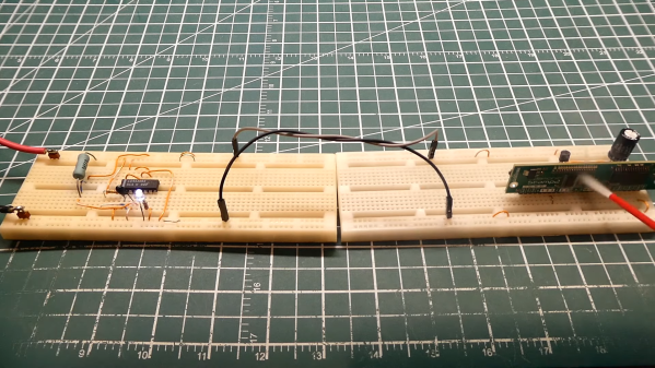
As with all things electronic, there are tradeoffs, which [0033mer] addresses in some detail in the video below. The basic setup for his use case is a PIC-based sensor — temperature, for this demo — that would be mounted in some remote location. The microcontroller needs to be powered, of course, and also needs to send a signal back to a central point to indicate whether the monitored location is within temperature specs. Both needs are accommodated by a single pair of wires and a tiny bit of additional circuitry. On one end of the twisted pair is a power supply and decoder circuit, which sends 9 volts up the line to power the PIC sensor. The decoder is based on a CD4538 dual monostable multivibrator, set up for an “on” time of one second. A trigger input is connected to the power side of the twisted pair going to the sensor, where a transistor connected to one of the PIC’s GPIO pins is set up to short the twisted pair together every half-second. Power to the PIC is maintained by a big electrolytic and a diode, to prevent back-feeding the controller. The steady 0.5-Hz stream of pulses from the sensor keeps resetting the timer on the control side. Once that stream stops, either through code or by an open or short condition on the twisted pair, the controller triggers an output to go high.

It’s a pretty clever system with very simple and flexible circuitry. [0033mer] says he’s used this over twisted-pair wires a couple of hundred feet long, which is pretty impressive. It’s limited to one bit of bandwidth, of course, but that might just be enough for the job. If it’s not, you might want to check out our primer on current-loop sensors, which are better suited for analog sensors but still share some of the fault-detection features.

Continue reading “Simple CMOS Circuit Allows Power And Data Over Twisted-Pair Wiring”

Adding In-Game Reset To Classic Playstations

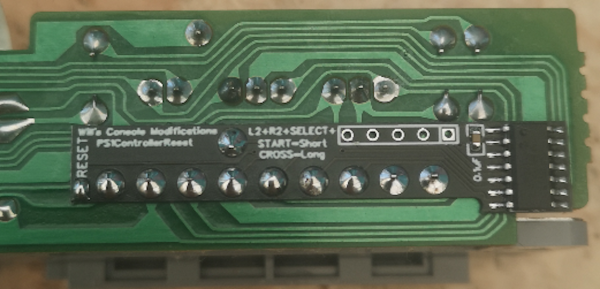
The first Playstation is quickly approaching three decades since its release, and while this might make some of us who were around for that event feel a little aged, the hardware inside these machines isn’t getting any younger either. Plenty of people are replacing the optical drive in the original hardware with an optical drive emulator as they begin to fail, and with that comes the option for several other modifications to the hardware like this in-game reset mod.

In-game reset is a function that allows a console to be reset via a controller button combination rather than pressing the console’s reset button directly. Especially for devices modified with either the XStation or PSIO drive emulators, this can be a handy feature to have as this method can more easily take the user back to the emulator menu as well as physically reset the device. The modification is a small PCB which attaches to the controller port and, unlike previous versions, only requires a single pin to be soldered to the Playstation’s control board.

If you’re someone who enjoys playing games on original hardware rather than a patchwork of emulators, this could be an excellent addition to your PS1 that still allows most of the original feel and experience the PS1 offered. The drive emulator can greatly expand the range of the hardware as well, much like this NES cartridge which similarly expands the capabilities of that much older system.

Add-On Makes ESP32 Camera Board Easier To Program

Don’t you just hate it when dev boards have some annoying little quirk that makes them harder to use than they should be? Take the ESP32-CAM, a board that started appearing on the market in early 2019. On paper, the thing is amazing: an ESP32 with support for a camera and an SD card, all for less than $10. The trouble is that programming it can be a bit of a pain, requiring extra equipment and a spare finger.

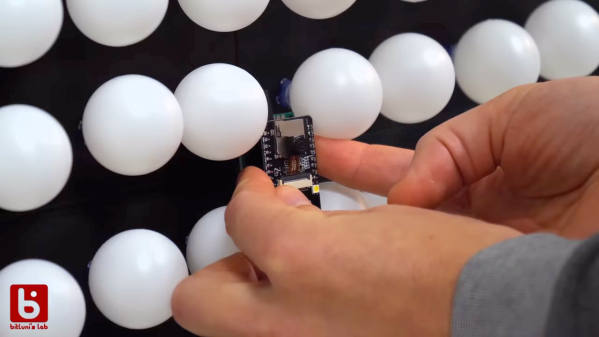
Not being one to take such challenges lying down, [Bitluni] has come up with a nice programming board for the ESP32-CAM that you might want to check out. The problem stems from the lack of a USB port on the ESP32-CAM. That design decision leaves users in need of a USB-to-serial adapter that has to be wired to the GPIO pins of the camera board so that programs can be uploaded from the Arduino IDE when the reset button is pressed. None of that is terribly complex, but it is inconvenient. His solution is called cam-prog, and it takes care of not only the USB conversion but also resetting the board. It does that by simply power cycling the camera, allowing sketches to be uploaded via USB. It looks to be a pretty handy board, which will be available on his Tindie store.

To demonstrate the add-on, he programmed his ESP32-CAM and connected it to his enormous ping pong ball video wall. The video quality is about what you’d expect from a 1,200 pixel display at 40 mm per pixel, but it’s still pretty smooth – smooth enough to make his interpretive dance moves in the last few minutes of the video pretty interesting.

Continue reading “Add-On Makes ESP32 Camera Board Easier To Program”

Reset Your Router The Modern Way

Many Hackaday readers will be settling back into their lives after a holiday period crammed into some family matriarch’s house along with too many assorted relatives, having given up their speedy internet connection for whatever passes for broadband wherever Granny lives. The bargain-basement router supplied by the telephone company will have spent the period wilting under the pressure of a hoard of teenagers watching other teenagers inanities on YouTube, and the Christmas ritual of Resetting The Router will have been performed multiple times.

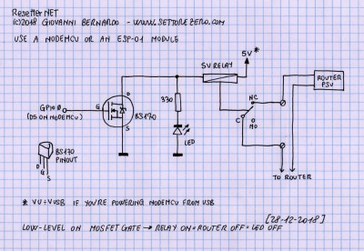
A very simple schematic for the resetter.

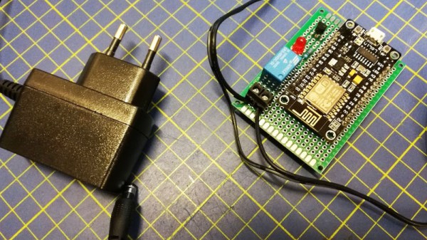
Wouldn’t it be nice if your router simply reset itself every time it crashed or the Internet connection went down? [Cyb3rn0id] has a solution (Italian original here), in the form of an ESP8266 that pings an online service every few seconds, and turns the router off and on again via a power relay in the event that the ping attempt is repeatedly unsuccessful. It’s brilliantly simple, requiring only a single GPIO and a MOSFET to fire the relay with an LED indicator for good measure, and it’s built upon a piece of prototyping board. The router power is switched on the low-voltage side for safety.

The software is pretty basic and has the WiFi credentials hard-coded into it, so we’re guessing a version with a web interface could be built. But as a personal device for easing the pain of router crashes it gets our vote despite that shortcoming.

This isn’t the first router resetter we have seen here, but a previous model still required human intervention.

Softly To Sleep, My Raspberry Pi

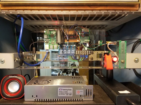
For all their capacity, shutting down a Raspberry Pi can be a bothersome routine depending on how you have it set up — historically and abrupt cut to the power risks corrupting the SD card. [madlab5] had to make a few changes to a Pi running in headless mode, requiring them to access it externally to shut it down to prevent any damage from pulling the plug. So, why not take the opportunity to whip up a soft shut-down switch?

This is a great beginner project to get one accustomed to working with a Pi. With this in mind, [madlab5] went through two revisions of this idea: the simple way, and the fun way. For the simple way just press the button and the Pi activates a script which shuts it down in thirty seconds. Job done. But, realizing there may be a few circumstances where they’d need more functionality, [madlab5] decided to take a second swing at this.

[madlab5]’s fun way involves a button with a built-in LED and a speaker to blare an announcement that the Pi will self destruct shut down after a short time. Setting the switch up this way takes a little more doing, but you get to add a little more character to your Pi with a custom shutdown report, as well as the option to cancel an accidental button-press.

For any newbies out there, [madlab5] is kind enough to provide their code and diagrams in their blog post. If remotes are more your thing, we have also featured a similar beginner project to shut down your Pi.

[via /r/Raspberry_Pi_Projects]

Amazon Dash Reboots Your Pi

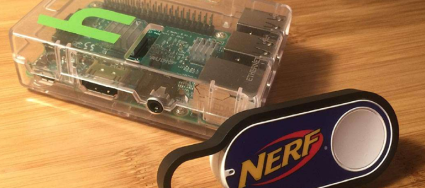
We all know feature creep can be a problem in almost any project. A simple idea can often become unusable if a project’s scope isn’t clearly defined in the beginning. However, the opposite problem sometimes presents itself: forgetting to include a key feature. [Zach] had this problem when he built a Raspberry Pi magic mirror and forgot to build a physical reset/shutoff switch. Luckily he had a spare Amazon Dash button and re-purposed it for use with his Pi.

The Raspberry Pi doesn’t include its own on/off switch. Without installing one yourself, the only way to turn off the device (without access to the terminal) is to unplug it, which can easily corrupt data on the SD card. Since [Zach]’s mirror was already complete, he didn’t want to take the entire thing apart just to install a button. There’s already a whole host of applications for the Dash button, so with a little Node.js work on the Raspberry Pi he was able to configure a remote-reset button for his mirror.

This is a similar problem for most Raspberry Pi owners, so if you want to follow [Zach]’s work he has done a great job detailing his process on his project site. If you’re looking for other uses for these convenient network-enabled buttons, he also links to a Github site with lots of other projects. This pizza button is probably our favorite, though.

Don’t Take Photos Of Your Arduino 101 Either, It’s Light Sensitive

Wafer level chips are cheap and very tiny, but as [Kevin Darrah] shows, vulnerable to bright light without the protective plastic casings standard on other chip packages.

We covered a similar phenomenon when the Raspberry Pi 2 came out. A user was taking photos of his Pi to document a project. Whenever his camera flash went off, it would reset the board.

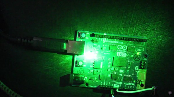
[Kevin] got a new Arduino 101 board into his lab. The board has a processor from Intel, an accelerometer, and Bluetooth Low Energy out of the box while staying within the same relative price bracket as the Atmel versions. He was admiring the board, when he noticed that one of the components glittered under the light. Curious, he pulled open the schematic for the board, and found that it was the chip that switched power between the barrel jack and the USB. Not only that, it was a wafer level package.

So, he got out his camera and a laser. Sure enough, both would cause the power to drop off for as long as the package was exposed to the strong light. The Raspberry Pi foundation later wrote about this phenomenon in more detail. They say it won’t affect normal use, but if you’re going to expose your device to high energy light, simply put it inside a case or cover the chip with tape, Sugru, or a non-conductive paint to shield it.

EDIT: [Kevin] also tested it under the sun and found conditions in which it would reset. Videos after the break.

Continue reading “Don’t Take Photos Of Your Arduino 101 Either, It’s Light Sensitive”