I’ve taken lots of reference photos for various projects. The first time, I remember suffering a lot and having to redo a model a few times before I got a picture that worked. Just like measuring parts badly, refining your reference photo skills will save you a lot of time and effort when trying to reproduce objects in CAD. Once you have a model of an object, it’s easy to design mating parts, to reproduce the original, or even for milling the original for precise alterations.
I’m adding some parts onto a cheap food dehydrator from the local import store. I’m not certain if my project will succeed, but it’s a good project to talk about taking reference photos. The object is white, indistinct, and awkward, which makes it a difficult object to take a good photo for reference use in a CAD program. I looked around for a decent tutorial on the subject, and only found one. Maybe my Google-fu wasn’t the best that day. Either way, It was mostly for taking good orthogonal shots, and not how to optimize the picture to get dimensions out of it later.
There are a few things to note when taking a reference photo. The first is the distortion and the setup of your equipment to combat it. The second is including reference scales and surfaces to assist in producing a final model from which geometry and dimensions can be accurately taken. The last is post-processing the picture to try to fight the distortion, and also to prepare it for use in cad and modeling software.
Set-Up & Distortion:
It’s important not to try to be a good photographer, in the traditional sense, when taking a reference photo. We don’t want an interesting photo. We want a photo that’s as evenly lit, undistorted, and scaled as possible. If we took a photo of someone’s face using these methods, it would be terribly unflattering.
The first bit of equipment to help us is a camera whose lens does not distort the photo. Unfortunately, I am not a photographer so I cannot tell you what kind of lens combination is going to give you the best result. Perhaps someone can help out in the comments? However, I find that the lenses that come with regular point and shoot cameras or phones are usually pretty good for this. They are designed so that grandma (or Gerrit) can get the picture expected without having to know what fish-eye or barrel distortion is.
The real trick is just to back up from the subject. The further from the item in question, and the smaller it is in the picture, the less the overall lens distortion will affect it. Obviously, backing away from the object will lose some resolution, so it depends on what you need it for. For most applications, it is okay to lose some pixels for the sake of greater accuracy.
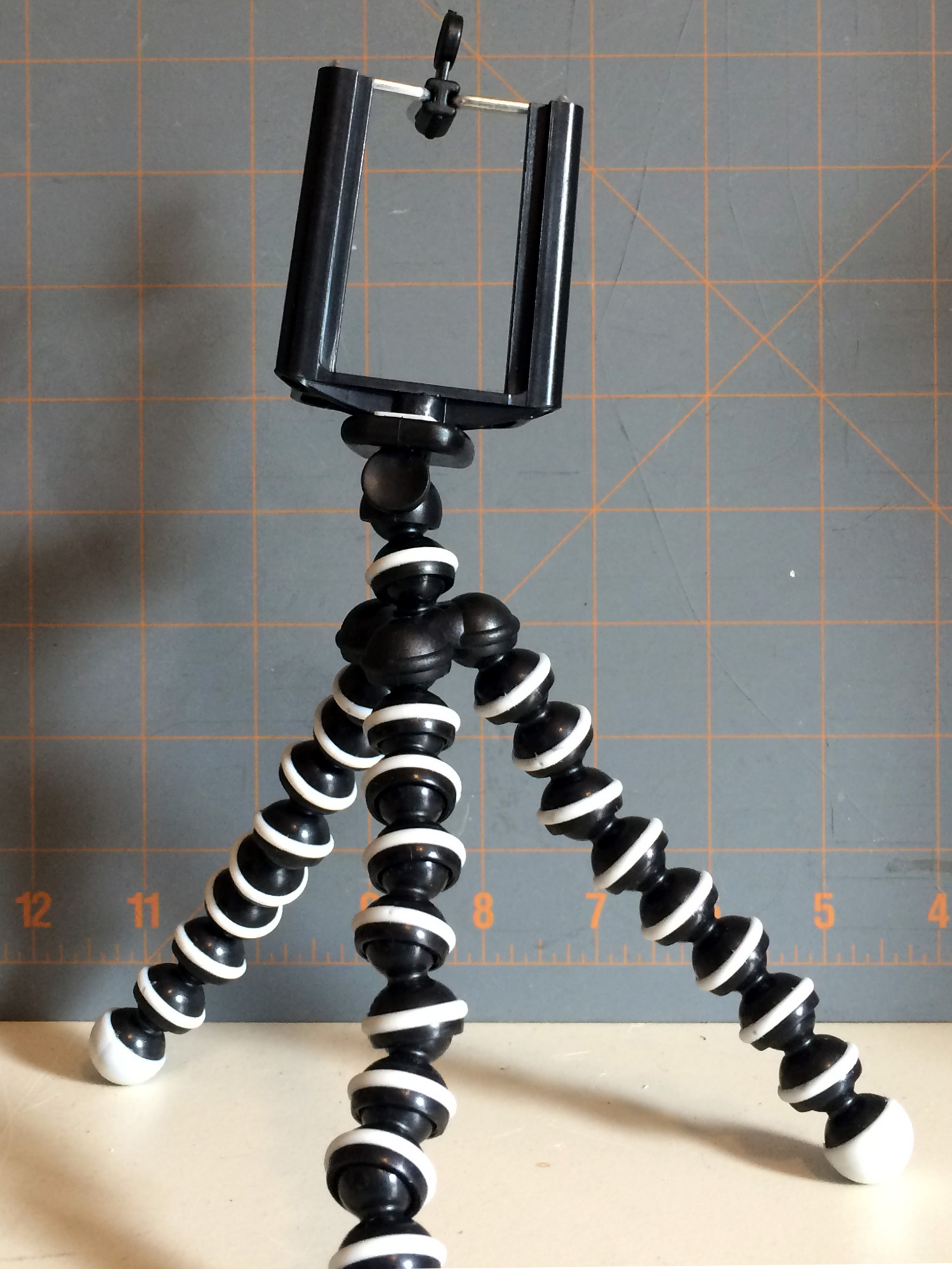
Next is skew and perspective errors. You want to take a photo as dead-on as possible. If successful, the only errors will be lens distortion and parts of the object getting smaller as they vanish into the horizon. A tripod isn’t necessary, but really helps. I have a three-dollar adapter for my phone that allows me to use it as a camera on a cheap tripod. It’s not silky smooth to adjust, there may be some swearing, but it will work for most things. We’ll set the camera level with the most important feature we are trying to capture. Setting it up to get the center of the object isn’t necessarily as important, because the further our point of interest gets from the middle of the lens the more distortion and perspective errors it will receive.
Lighting is also important. You can use a harsh light to some effect to show off a detail using shadows, but it is important to note the length of the shadow and the direction of the light on paper to assist later when pulling dimensions. A bright even light that doesn’t wash out the shadows on the part is best. Think of early art projects. When you shaded in a cube or sphere you wanted the smoothest gradient possible. If you over exposed the death star you would just have a white circle on a black backdrop, and all those Bothans will have died for nothing.
Reference Scale:
I use a few things to make a proper scale for my pictures. The most useful is a grid. It can be of arbitrary dimensions, as its main purpose is to help us set-up the photo and remove the distortion later in the process. Since it sits behind the object, it’s hard to tell what size the grid is without employing unnecessary trigonometry. I typically use a cutting mat that conveniently came with a grid painted on it. It is pretty easy to find a grid pattern online to print if needed. It’s nice to have large easy-to-see squares rather than small ones.
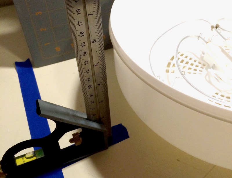
This process is not extremely accurate, but with care and luck one can sometimes get within a millimeter. If we supplement these with some caliper tricks, we can get even better. I like to take a graduated combination or machinist’s square and just set it beside the object. A wooden ruler will do as well.
It’s good to use the square to set the part upright to the table so that it’s orthogonal to the camera. I like to use a laser level to project a line from the camera to the object. This takes all the guesswork out of the equation.


Photo Tips:
- Don’t try to do it all in one photo. If you need the outline of an object. Set-up a photo to take the outline. If you need the interface on that object, set-up a photo just for that. You can always set-up more reference planes in your CAD software. It’s usually quicker and delivers a better result to take two photos, than to force one to do two different jobs.
- If there is information on the device that can be harvested without the help of the reference photo, record it separately. Don’t try to lift dimensions and information from the photo if it can be taken in a more accurate way.
- Clean the object thoroughly. I’ve wasted some time decoding a feature that was actually just dirt or oil on a part.
- If it’s a really strangely colored or glossy object and you can afford to ruin it, spray paint it a matte grey color.
- If it’s a thin, flat object, a few readers imparted this useful trick in the caliper post, a flatbed scanner will do an amazing job of reproducing it in two dimensions.
- Make sure to expose the photo for the maximum amount of greys and definition on the object. We don’t want any big highlights or big shadows. It may make the photo boring, but that’s okay.
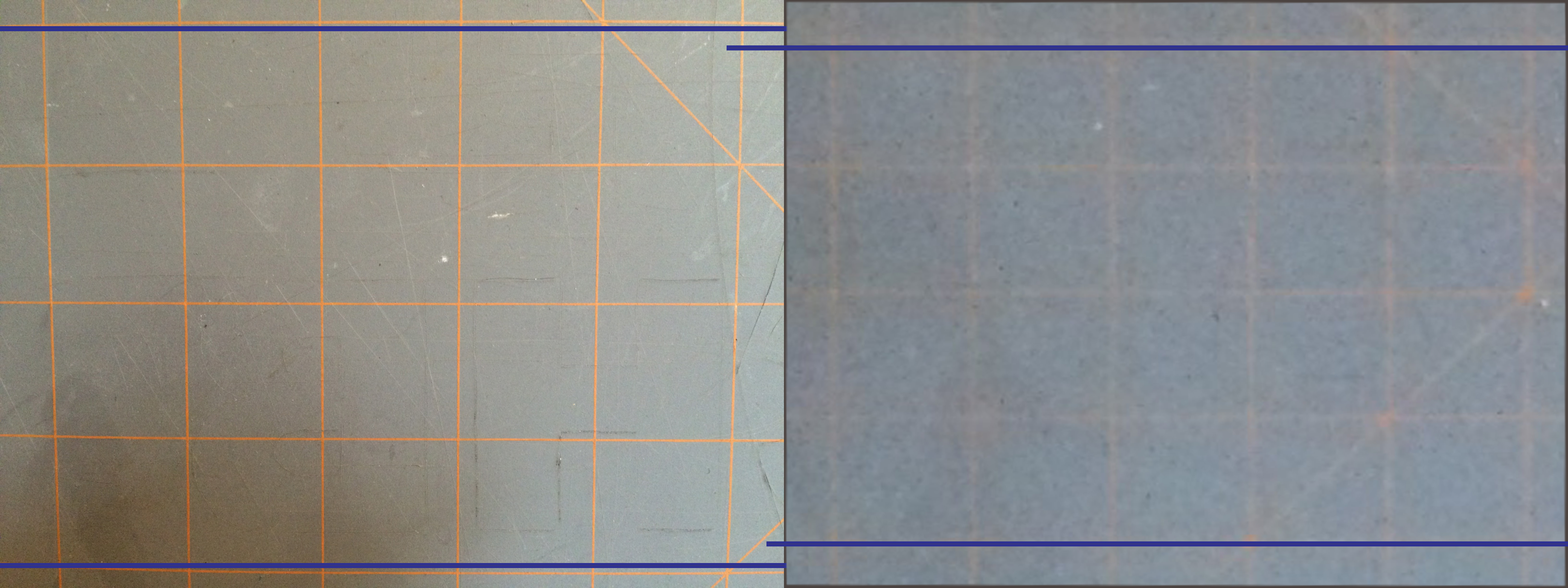
- If the object is really big and it obscures the grid, there is a trick to still get the distortion out in the plane needed. Lets say you want the outline of an object taken at its center plane. Take a photo of the object. Now, mark the center of the object on the table, and mark the edge of the grid. Take the object away and then move the grid to the center of the object using the marked lines. Take a picture without moving the camera set-up. You now have a picture of the distortion at the center of the object. Correct the grid photo and then correct the original photo the same way to get an accurate outline.


Post-Processing
In post processing, we will want to.
- Remove the distortion.
- Fix the lighting.
- Crop the photo properly for CAD software.
I typically use Photoshop to do my photo editing, but GIMP will work just fine. Both GIMP and Photoshop now include a camera distortion filter. You want to use this one first before moving onto the perspective errors that may have shown up in the picture. This is where the grid we placed behind the object comes in handy. The goal is to straighten any grid lines which are concave or convex. Once we have done this, we’ll have good lines for the next step.
The next step is to use the transform tools to distort the photo until all the lines are square to each other. It is likely that they are either a parallelogram, trapezoid, or strange combination of the two. If it is really extreme, you are better off retaking the photo and spending more time on set-up. If you really nailed it you can skip both these steps and that will be the photo which has the most accuracy.
The lighting in the photo may be off. Use the Levels tool to change it until we get the smooth gradient we are looking for. It may be tempting to wash out the photo, or to even it out so that the whites are white. Modern product photography has taught us that bright clean looking photos are what we strive for. This is not our goal. We are trying to extract geometrical information from the photo. What we want is a photo where the gradients of the shadows are most defined and the edges stand out clearly from the backdrop. It may look a little dark or washed out, but if you can clearly see everything it is done right. Try to think of old black and white educational photos from textbooks.
Last is cropping the photo. We want to crop as close as possible to the object as we can. I zoom in until the edge of my crop just touches the pixels of my object. We do this because we will set a dimension we want the software to size the photo to in our CAD software. If we have extra pixels bordering our object it will throw off the measurements we take.
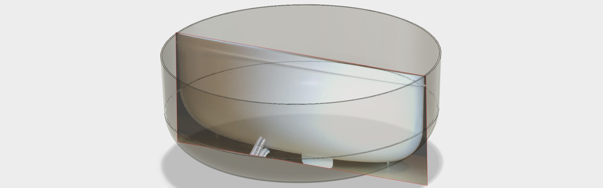
Once you have cropped the photo, I also recommend distorting the photo to match the aspect ratio of the original object. For example, if you have taken a photo of a cylinder that is 10 inches in diameter and 15 inches tall, make sure the photo, if taken from the front, is to a perfect 2:3 ratio. If the perspective errors were removed successfully in the set-up and post-processing phases we should have a really close picture of the object at that point.


Conclusion
Hopefully after all the work we have a photograph that we can use in our modeling software of choice. It varies between them but the standard workflow is to make a plane and draw curves in a sketch. After that it’s a simple matter to extrude or revolve them into useful surfaces. For work that’s not in three dimensions, such as getting a board outline, you can also import the image into a vector program like Inkscape or Illustrator and trace the outline. Once you have that you can export it into a format your CAD software likes.
I hope this was useful. I’m sure many of you have solved these problems in your own way. What tricks and methods do you use to get a good reference photo?


The obvious solution here is ‘Banana for scale.’
As long as you have a reference that precisely matches the International Prototype Banana.
That reminds me… my banana is due for calibration.
I’d hate for it to be demoted to ‘Reference Only.’
My banana went out a calibration because of the potassium isotopes. I’m switching to cucumbers from now on.
Seriously though; for some reason your post made my day.
Or point cloud based laser scanner.
The way to deal with perspective and lens distortion is to calibrate your camera. There are no lenses on the market that will not distort your scene and unless you are taking the pictures really dead-on (outside, large objects, etc.), you will always have perspective distortion.
There is a good tutorial on how to calibrate your camera here:
http://wiki.ros.org/camera_calibration/Tutorials/MonocularCalibration
There is also a famous Matlab toolkit for this (should work with Octave too):
http://www.vision.caltech.edu/bouguetj/calib_doc/htmls/parameters.html
Then you rectify your image – that will correct for the lens distortion. Lines will be again lines and not arcs. Finally, you can even do a homography and re-project the image as if it was taken dead-on, correcting for perspective distortion. All you need is a rectangle in the scene with known dimensions so that it is easy to find the image correspondences needed for this. This is easy to do using OpenCV, I think ROS has a tool for it too.
Once you have done this, you can directly measure the dimensions and angles from the photos. However, you will get them in pixels only. If you want milimeters/inches/whatever, you need to do one last step and that is to figure out the size of your camera pixels in real world units. That is easy – take a dead-on image of a ruler and count the number of pixels per a unit of distance. Division will give you the scaling factor to convert from pixels to mm you need. Don’t forget to do it for both horizontal and vertical axis, because most cameras don’t have square pixels!
One last note – if you are using a camera with a zoom lens, don’t forget to fix the zoom. Moving the zoom changes the focal length of the lens and will invalidate your calibration.
It’s correct for the most part that there are no lenses on the market that will not distort your scene, but laser scanning a point cloud is not “lens based” in the same way as a stack of camera lenses, focusing to a flat sensor so it is largely immune to that type of distortion.
Laser scanning is not very usable unless you are ready for doing a ton of post-processing. The point cloud is literally just that – a point cloud. Including all noise, mess and tons of data you don’t want. If you want to actually take measures from it or convert it to something useable in CAD, you will need to do a lot of manual work. The meshes that come out of these scanners after meshing the point clouds are something that you can 3D print, but rarely have the accuracy needed for CAD use out of the box. There is some specialized software that permits to recover 3D primitives from the scans, such as finding planes or cylinders, but that is fairly expensive.
Photos with a lot of fiducials and dimension references are easier to work from than a point cloud scan. Scans are good for very irregular, “organic” objects that are difficult to measure otherwise, but otherwise an enormous pain to use.
Converting “real world” to CAD is indeed tricky. RapidWorks is one example of a software that works to convert raw data into CAD data but I wholeheartedly agree that a point cloud is just a starting point. But it is at least a true capture of real world geometry. You could always load the point cloud data into something like MeshLab (http://meshlab.sourceforge.net/) and scale it accurately and automatically convert it into meshes. Then take accurate measurements from that, right from your CAD program of choice, even SketchUp or the like. You can also, with accurate enough scan data, scale that way, way up. I have seen this accurately capture entire rooms.
A good trick to avoid distortion is to use a regular flatbed scanner (as long as the item fits on the scan surface).
And when it _is_ too big: http://hackaday.com/2015/09/09/smart-phone-camera-turns-laser-cutter-into-hi-res-scanner/
I forgot about that! I’m not going to use a scanner or a laser cutter but a smoothly rotating tripod was something I was going to make for panoramas. I know I’m way off topic, but thank you Elliot that reminded me of a project that never left the napkin it was written on.
Well done and thought out.
If you shoot in RAW mode, you can import it to Darktable. Darktable has a lens-correction filter, which takes metadata from the photo that identifies your camera, lens, and exposure settings, and corrects the image for any geometry or chromatic aberrations.
Just FYI, darktable is Linux (and OSX) only, unless someone wants to step in and port it to Windows. It’s also unclear to me that it will completely eliminate all artifacts though. I mean if you are shooting at, say, 10 mm focal length, will it actually correct for that?
Oh, also. ImageMagick can also perform loads of image corrections and is extremely versatile and scriptable.
Here’s an example / walk through: http://www.imagemagick.org/Usage/lens/
It is also linux native but can be run on windows through Cygwin.
ImageMagick has native Windows builds as well, compiled with VC++. They’re near the bottom of the download page.
That’s correct. The windows version of IM doesn’t play nicely with other linux programs under windows without Cygwin though, unfortunately. So I generally opt for the Cygwin option but it has it’s quirks in terms of, well, you are using windows instead of linux so things like subtle filename and variable usage differences can be an issue.
Yes, ImageMagick is great for this. I use its affine transformation mode to remove perspective from old photos of WWII vehicles, for both scale modelling and fullsize vehicle restoration purposes. For example I may find a particular three-quarter side view picture of a truck. I then transform the photo into a plan/elevation/front/back view as required, scaling/transforming at 1mm per pixel to the the vehicle’s measurements. I then load the transformed image into my old CAD program and overdraw it. This way I can get the correct placement and dimensioning for camo patterns, stencilling, markings or other details I want to scratchbuild.
A profiling tool can be useful. Get a Contour Gauge.
Proper lighting is as easy as buying one of those LED strips, cutting it up and mounting it to an aluminum backing. You can put a diffuser on front, but it doesn’t matter. I use 2 of these for taking pictures of PCB’s.
Use a LOT of light, and the smallest aperture you can. I usually have my f-stop around 16 or so. You want the entire object to come in nice and crisp.
You can also use point-cloud software, which can give good results but for best results it requires prep.
And Gerrit, it is terribly difficult to get a hold of you, like no email address or contact page (I wanted to discuss 3D printer things with you).
Great article, im going to use the grid idea for sure.
After you get your model done, print a 1:1 scale drawing out on paper, cut it out and check fit against the original part. This saves a lot of time over 3d printing to get a reality check.
Photogrammetry: measurement using photos. It is my favorite engineering technique, thank you for the article!
In that case you would most likely enjoy ”OSS Briefing film – Iconography’ a detailed two-part introductory film by the USAAF on how WW2 photo intelligence was done. Using a single oblique aerial photo of an enemy installation, it showed how scale and details can be extracted so a plan and elevation can be generated. Using a device called an iconoscope holding a celluloid tracing of the recon photo set at the correct ‘tip’ and ’tilt’ of the camera aircraft,t the image was projected onto a flat surface where the objects then lost their perspective and thus be scaled and drawn. Unfortunately this interesting film was available on a site called ‘realmilitaryvideos.com’ which is no longer functioning, and I havent’t been able to find it on Youtube, but it’s excellent viewing if you manage to track it down.
Just tried again and Google’s amazing memory does have it after all, if you search for the film and click the ‘Videos cached’ dropdown. :)
There is some pretty good OpenCV Distortion Correction code floating around the web. Take the 10+ calibration photos of a chessboard, get your calibration matrix, and run the undistort python script for OpenCV. Has worked great for me so far, and you dont have to take the photo from across the shop.
If you are in a hurry, the Polarr google app will also correct for lens distortion, without calibration photos. (just include your grid behind the subject.
I actually prefer to break down the object into primitives like circles, squares, cylinders, bars etc, take these measurements, rounded edges aren’t too difficult. Most 3D design apps let you directly draw primitives and chances are that the actual object was created that way.
When I do take photos I use my lenses at longer focal lengths. Usually any dslr with a 50mm or 85mm prime lens is virtually distortion free. Point and shoot camera’s often have barrel distortion on the wide angle and pincushion at the long zoomed in setting, so pick a focal length in between. Usually 50mm to 85mm 35mm sensor/film equivalent works best.
Be careful with focus stacking though, some lenses change in focal length giving a size difference at the same distance.
I use adobe illustrator to move and size side, front and top view and use guides to line them up. I use the measure tool to get dimentions. I usually line them up and use one reference to make them to scale for all photos at once.
I often trace the 2D outlines using the pen tool and import them as eps vector drawings into the 3D package. Then it’s a matter of using extrude and boolean opperations to reproduce the object.
If an object is white or transparent with no references, you can use a beamer, projector, or laser guide to get some reference guidelines. Alternatively, you can use painters tape, cover the object and draw reference lines directly on the object. Especially with organic shapes this can help a lot, even for point cloud scanners.
Here’s an incredible video of someone who made a mini 3D printed replica Apple /// case entirely from pictures. Truly amazing to watch: https://www.youtube.com/watch?v=ITsdbaqbObY
Hugin does a fantastic job of correcting for lenses and perspective. I’ve used it for years both for panoramas and for reference photos.
http://hugin.sourceforge.net/