Let’s get it out of the way right up front: you still need to etch the boards. However, [Mikey77] found that flexible plastic (Ninjaflex) will adhere to a bare copper board if the initial layer height is set just right. By printing on a thin piece of copper or conductive fabric, a resist layer forms. After that, it is just simple etching to create a PCB. [Mikey77] used ferric chloride, but other etchants ought to work, as well.
Sound simple, but as usual, the devil is in the details. [Mikey77] found that for some reason white Ninjaflex stuck best. The PCB has to be stuck totally flat to the bed, and he uses spray adhesive to do that. Just printing with flexible filament can be a challenge. You need a totally constrained filament path, for one thing.
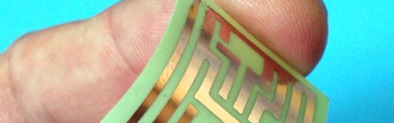
 There are several other tricks. The fabric PCBs are very flexible, although that has nothing to do with the flexible plastic, which is all removed after etching.
We wondered if you could print a “holder” with the pattern and make the printer pause once the holder was complete. Then you could put the board in the holder before resuming the print to lay down the resist. That would allow very close alignment and might make two-sided boards possible.
Of course, software to convert a Gerber or other common PCB file format to the required STL file would be nice. There is software to do that, but we don’t know if the result would be directly suitable for this process. At the least, you’d have to manually add the spacer bar and offset the pattern.
We’ve seen people use 3D printers to remove resist before, but apparently common 3D printing plastics don’t stick well enough to be practical. Even if you can’t print a real PCB, sometimes a mechanical mock-up is useful, too.


That instructable was published Aug 07, 2014. Clearly HaD is just reading the instructions for their time machine upside down.
A simple sharpie was replaced by a complex print head. Great achievement :-)
This make me wonder what other materials you could use in a 3D printer to get better resolution. In this example the traces seem to be about 50 mill thick which is only good for DIP.
Perhaps a syringe and fine needle with paint / ink / etch resist?
Excellent project, perhaps it will lead further.
Or a sharpie on a 3D printer? À la http://hackaday.com/2017/01/17/good-penmanship-with-a-3d-printer/
Laser which burns away a layer of etch resistant black paint?
Doesn’t even have to be black paint. Back in college, they made PCBs by coating the board with clear lacquer, etching that with a laser cutter, then finishing with a chemical etch to remove the unprotected copper.
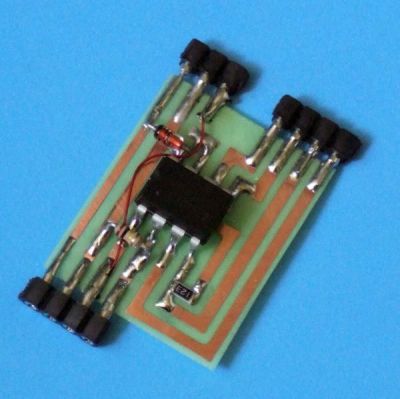
I wonder how it is possible to solder components to this circuit without melting the NinjaFlex substrate
The substrate is not NinjaFlex. NinjaFlex is only used to protect the copper from the etchant. Read the article.
Replacing a cheap, low-cost and reliable Sharpie with expensive, hard-to-apply flexible filament. Neat idea.
Not everyone has the manual dexterity required to draw circuits using a sharpie.
My 3D printer does have the manual dexterity required though. I’ve done toner transfer and I’ve done sharpie resists, and honestly neither is 100% foolproof, but I’d take either over printing ninjaflex on a substrate…
I thought i have read this somewhere some time ago, maybe it was Hackaday?
http://hackaday.com/2014/10/28/make-flexible-pcbs-with-your-3d-printer/
For 10 bucks a pop are you really expecting the editors to do some digging for each post, which may take up to minutes?
Could you 3d print on to a standard copper blank and etch with ferric chloride? Or would the etchant bleed under the plastic?
Yeeeessss. I’m making a bunch of 2″x2″ pcbs with boards that are as flexible if not more flexible than the one in the picture. After 13 etches I had pretty much quit, but this could revive me!
The “flexible PCB” substrate in this case is just thin FR4 fibreglass, which is a little bit flexible, but not comparable to the polyimide that people generally think of when they think flexible PCBs.
I must be missing something fundamental here.
What is the defined goal of flexible circuit boards? The endpoint to be desired?
If it is for some novel form of bend/torque sensing, or making the unit as light as possible, then that may be something, but adding non-flexible components to a flexible base as done here is surely going to lead to problems with the fracturing of component leads and solder joints. Something has to fatigue, somewhere. In the past, circuit flexing has been mitigated through the use of solid frames and epoxy potting with the Apollo AGC logic blocks being a good example.
Flexible circuits with non-flexible components.. I still don’t get it.
I was thinking the same but i think we were both thinking of constantly flexing boards… which would fail.
Imagine you wanted to put a PCB inside the walls of a coffee cup… make it, bend it into place ONCE.
or have a curved phone around your wrist as a watch…. produce it flat, bend it into its final position.
i guess thats the intended use?
Why bother with a 3D printer, when a 2D printer could work? Back in the mid-1990’s the Apple Ham radio club was using the “cardboard” setting on the current Apple printer after discovering the black ink would resist the ferric chloride etchant. They were using thin G10 and printing a photo of a circuit onto the board and etching. Results were decent from what I saw.
No problem is simple enough that someone, somewhere, won’t come up with a crazy, complex solution for it.
Will the resist be re-usable? After it is peeled off the etched board, can the flexible resist be pressed onto a new piece of copper-clad board to etch another copy of the same pattern?