Do your Mark 1 Eyeballs no longer hold their own when it comes to fine work close up? Soldering can be a literal pain under such conditions, and even for the Elf-eyed among us, dealing with pads at a 0.4-mm pitch is probably best tackled with a little optical assistance. When the times comes for a little help, consider building a soldering microscope from a Pi Zero and a few bits and bobs from around the shop.
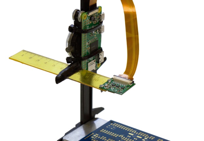
Affordable commercial soldering scopes aren’t terribly hard to come by, but [magkopian] decided to roll his own by taking advantage of the streaming capabilities of the Raspberry Pi platform, not to mention its affordability. This is a really simple hack — nothing is 3D-printed or custom milled. The stage base is a simple aluminum project box for heat resistance and extra weight, and the arm is a cheap plastic dial caliper. The PiCam is mounted to the sliding jaw of the caliper on a scrap of plastic ruler. The lens assembly of the camera needs to be hacked a little to change the focal length to work within 10 centimeters or so; alternatively, you could splurge and get a camera module with an adjustable lens. The Pi is set up for streaming, and your work area is presented in glorious, lag-free HDMI video.
Is [magkopian]’s scope going to give you the depth perception of a stereo microscope? Of course not. But for most jobs, it’ll probably be enough, and the fact that it can be built on the cheap makes it a great hack in our book.


Nice, but when will someone invent something for shaking hands? I have no problem with seeing 0402 but keeping them in place and not nudging with my hands is another matter. I’ve seen manual pick and place machine but it still looks like too much hassle and I would need to use solder paste instead of soldering iron.
What helps is keeping your hands supported on the table, good tweezers and loads of the sticky gel flux (not the liquid one – that one sucks for SMD work). The sticky flux will help keep the parts in place while you solder them.
OTOH, 0402 and smaller are hard to use by hand, there is no magic there. If you need to rework a few parts, it is doable, but for populating entire boards I don’t go under 0603 sized passives. The space you save is rarely worth the extra board manufacturing cost and hassle handling it due to the smaller parts.
I already use sticky flux, but it doesn’t help when I nudge part with soldering iron. I typically hold it down with the other hand but it still doesn’t help. Keeping hands on table doesn’t help because then only fingers are shaking. It’s not that big problem with 0603, but some “iron stabiliser” would still help. It’s only a “maybe someday” wish for now, on good day recently I managed to solder 0603 with transformer soldering iron.
Holding the component down with a weighted point probe (google ‘welders finger’) helps a lot. If you are using a corded iron, good cord support so you aren’t puling against it, helps. Adding some mass to the iron will reduce the shaking, and mounting the iron on a counterbalanced support might help if you have severe tremors, though that is only a guess.
Good body position is important. Drinking less coffee helps, as well. I am of an age, as they say, and can still handle (with a lot of optical help) 0603 without much trouble, and 0204 if pressed, but when doing so, EVERYTHING needs to be fixtured. When I was 18, I could work like an octopus, By the time I was 40, not so much. Now, not at all.
In the end, there are limits to the precision any of us can work to, at any age, as there will ALWAYS be minor tremors, due to the nature of how muscles work. Minimizing the length of the arm over which they work by bracing your hand helps a lot, but won’t eliminate the issue.
Right, I always try to plant the heel/side of my hand down firm, get a full finger pad grip on the implement and just roll it into position.
I found out that it’s even better to not touching 0603 with iron at all. Blob one solder pad with solder, put 0603 on pads with gel flux.
Put your iron tip on the side of the blob and the capacitor/resistor will centers itself on the blob pad. Then solder the other side normally.
Better done with a chisel tip of pad width at minimum.
Perhaps if you laid of on the Heroin your hands wouldn’t be so shaky.
Perhaps if you laid off on the Heroin your hands wouldn’t be so shaky.
Perhaps if you laid off on the Heroin, your hands wouldn’t be double clicking the Post Comment button.
B^)
It is heroin deficiency that make you shake.
Of course the real trick is to make sure your first soldering iron as a kid is one of those general purpose Webbers with about a foot of hot end and pinkie thick heavy duty cord on. Then the tip is moving in about one inch circles as you hold it, and you develop the coordination to plant the tip as it swings by the point you want to solder…
After that, getting an iron with only 3 or 4 inches sticking out of the handle, makes everything a piece of cake.
http://i.imgur.com/wfJLqf6.jpg
drinking steadies the hands
for eastern europeans at least ;)
I have had to stop work until the blinking red light goes off.
oh jesus i didnt know they did that. i reported my own comment haha
For holding SMT parts still I would recommend a weighted point clamp that basically holds your parts down like a finger from above. Something like this:
http://hackaday.com/2010/12/13/diy-clamp-helps-with-surface-mount-soldering/
If you shaking has that much of a detriment to your ability to function then you may want to see a doctor about it and he/she may be able to help you. In the case of intention tremor and no contraindications, something such as a beta blocker may help.
Maybe try to develop an exoskeleton glove that gives you ultra precise soldering skills by inhibiting some unwanted movements as an upcoming project? :-D Sounds like a fun challenge to get it light and ergonomic enough and still allow you to complete a normal workflow. could even find some applications for people who have parkinsons desease.
I was thinking of something along the same lines when I first read his post. Like a vibrational dampener for his hands.
With a pair of motors and a few stuff you build an XY support for the printed board, next you’ve simply to synchronize its movements with yours. That’s it !
I was expecting 0.4mm QFP soldering :)
The speed is amazing, but the quality of the color reproduction sucks. All it needs is a nice ring light with diffuser :)
.. Indirect illumination dome works better than ring with diffuser. I build my from ikea bowl.
How do you know? You’re assuming it’s being illuminated by white light due to the inset camera image, but *that’s been white balanced*. There’s no absolute ground truth here.
The Pi camera can have it’s white balance adjusted as well, it just probably wasn’t worth the bother.
When people were review-ing USB microscopes one of the complaints was the delay, many were too slow to be useful, even if the image quality was good.
How is the latency on this one, considering it is streaming via network?
I should have checked the text: “In an attempt to address this issue, I decided to build my own soldering microscope based on a Raspberry Pi Zero W and a camera module. The microscope is capable of streaming Full HD video directly to an HDMI monitor with practically no latency, which is perfect for soldering. But also over WiFi with a latency of less than half a second, which is pretty good for board inspection”
Try some of the other cameras available with 12 mm threaded bodies and you can use extenders and other lenses to alter the optics. I’ve got a threaded extender so I can alter the focal point and use it as a macro lens. This stuff is cheap and easy to get from the far east as it’s used in a lot of cheap CCTV cameras. So easy to experiment with.
Then along with focusing with the lenses you can play with software enlargement and even filters to adjust the image to make it clearer.
I wonder if it’s possible to apply software filters to make things easier for the partially sited or colour blind.
I had a friend in the long defunct Intel consumer level toys lab of the 90s. They had a USB microscope which was pretty much a webcam on some microscope lenses, not sure if it ever made it to stores. Other than Pi bits in your maker stock supplies why do I want this more than straight USB to the computer we all probably have?
The camera is MUCH better quality and much faster, especially at high resolution. Many cheap USB cameras/microscopes drop down to 15fps or less when running FullHD, which is okaish for inspecting the board (or using the thing as a microscope) but terrible for actually soldering under it.
The QX3, you can snag them at yard sales sometimes.
Yeah, I bought mine at a 2nd hand store for $4. The software that goes with the camera/microscope sucks (it is for entertaining children), but I found on the web a decent way to make it work with Linux.
I brought one from Aldi for $30
I have tried a PC based USB microscope for soldering – and it basically sucks. Not because of the latency (if you can a decent camera) but because of the poor ergonomics. You have to look at the screen not at what you are working on, the brain needs to get used to that first and it will always feel awkward. I don’t have that feeling when using an optical microscope – I guess the proprioception sense gets fooled by looking in generally the same direction as the work as opposed to using a monitor.
And the lack of depth perception is the killer there – if you try even a cheap stereo microscope you will never want to go back to trying to fumble your way using a screen.
On the other hand, these digital microscopes using screens are great for showing what you are doing an audience or for board inspection.
” if you try even a cheap stereo microscope you will never want to go back to trying to fumble your way using a screen.”
I use an expensive stereo microscope at work, and I close one eye when using it, because trying to get both eyes (different Rx) to focus on the board isn’t worth the bother.
Theoretically, you close the right eye, focus with the left, then twiddle the right eyepiece until right focussed….
… unless you’ve got mass astigmatism differences or the collimation is complete pooched.
I look through the left eyepiece with my right eye!
B^)
I’ll try it the way you mentioned, no one ever taught me how to focus one.
You can use many microscopes, especially better ones, with your vision correction for distance. You might need to flip eyecups out of the way, depending on design. Some less expensive ones have insufficient eye relief to use with glasses the view plane is too close to the eyepiece surface.) I lust after a Mantis for this reason, but do fine with my Nikon (25mm relief).
The other thing to check during setup is the interpupilay distance. After getting clean focus, readjust the didtance between the eyepieces. If this is not right, it can be very difficult or impossible to fuse the images. If it is close, but not right, the strain can make focus more difficult.
Using a stereo scope as a cyclopes is not the point :-) I have a big stereo that is OK. To use the camera port, it diverts the left optical path and my speed soldering drops to about 1/10th. I make how-to videos with it and can not get the smoothness and speed in the videos that I get in stereo.
In stereo, I just focus for the eye on the fixed eyepiece and then use the adjustable for the other eye. Or, if others will be using it too, I wear my reading glasses. The eye-relief is plenty to allow glasses.
Given a Pi0+camera isn’t exactly expensive, I wonder how effective it would be to make a stereoscopic setup by wiring two up that feed a suitable (fixed) headset?
A cheap smartphone would have the screen for you there as if lloking via a magnifying glass? tinyurl.com/lp3cwmc
Actually, I use my phone for looking in small dark corners, the macro focus is pretty good and can get 2-4X magnification, or also snap the pic and zoom and squint.
I feel somewhat embarrassed having to ask this but what’s the thing he’s using first to apply what I can only assume is solder flux? It looks like regular solder but isn’t melting into a metallic liquid.
I think it is just solder tin that he dipped in liquid flux and then uses the wire to spread out the flux – I do it with the thicker sticky type of flux all the time
You’re probably looking at the nozzle of his flux dispenser (probably some sort of blunt hypodermic needle), he dropping a bit of (colourless) liquid flux on to the board before melting some solder on to a pad that he uses to hold the component on to later.
I have an $18 ebay usb pen microscope on my CNC streaming via webrtc on a pi with very little lag over the local wifi network. I like the ingenuity, but it’s not necessarily the best or cheapest route using the pi camera.
I agree with the whole depth perception thing etc. I used to use a travelling stereo microscope, and it was great. By the by, those with shaky hands, I would assert (on the evidence of my own experience) that shaking hands do steady if you can watch the much magnified tips of your tweezers, fingers, soldering iron and so on.
I wonder if it would be worth an augmented reality / VR headset, two USB cameras to provide stereoscopy ? Actually, if it is the difference between being able to pursue a hobby and everything being too dang small to do any more, it would be priceless. Well, a hundred quid or so priceless.
For my part, still waiting for the eBay search for an affordable bench stereo microscope to come up with a hit (in the UK).
Keep an eye on Greenweld too in case any turn up surplus.
Keep an eye on educational surplus for dissecting microscopes, since the schools have pretty much quit doing anything icky. (Same for wet chemistry supplies. They now do micro-chem or nothing at all.)
I’m waiting for someone to come up with a soldering waldo. Easy to take the tremors out of that.
Where’s Waldo?
What does it take to convert a used pair of 10×30 binocs into a stereo scope anyway, take the objectives off and remount them spaced off on 20mm slice of tube or something??? That and rigid mounting (Hoseclamp to stick)
For those experienced in it : these kind of things need regular cleaning, yes ? Won´t the solder fumes, and the fumes due to the flux impregnate the lenses over time ? Or the use of a fan sucking the smoke is enough ?
I accept the extra surfaces and use a protective plate in front of the objective. A fume extractor is a good idea as well, for many reasons.
I have one that has been used by 5 years without any attention to the objectives. No visible effect. One like this but with an LED lighting ring: http://www.ebay.com/itm/7X-90X-Trinocular-Stereo-Boom-Zoom-Microscope-Fluorescent-Light-/400429169625?hash=item5d3b703bd9:g:o~4AAOSwXeJYENbD
thanks! One of those would be nice, but funds are somewhat limited for now ….Will need to cobble something like this article to see how it works. Would be nice to be able to use some cell phone cameras in a build like this
Before you buy one, check if it works on the phone in cyanogenmod, in which case there’s probably enough tech info around to use it. If not, you could be on your own.
Nice Gear.What is considered a useful magnification range for SMD work? Does one Really need 7-90x or is 7-45x sufficent?
I’m working on almost the exact same setup myself. Already have the same setup for read-only filesystem, although my plan was to use write a python script on top of the “picamera” library to control the streaming. I’ve got a USB numeric keypad that I’m going to use to control the camera functions (exposure, shutter speed, “digital zoom”, if needed). since the filesystem is read-only, I wasn’t going to do anything special for power other than a switch. For the camera, I got a arducam raspi camera with a CS mount lens, this allows for easy (coarse) close-up focusing adjustment.
My hangup has been creating a good adjustable Z-axis and stand on-the-cheap. Using a dial caliper in place of a standard rack-and-pinion is a clever hack! I wonder how trouble the HDMI cable causes though, it seems like it would have a tendency to drag it down.
Am I the only one who misread this as “Piezo Microscope”?