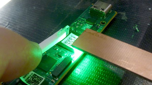
Tiny Prisms Let You See What Lies Beneath A BGA Chip

Compared to through-hole construction, inspecting SMD construction is a whole other game. Things you thought were small before are almost invisible now, and making sure solder got where it’s supposed to go can be a real chore. Add some ball grid array (BGA) chips into the mix, where the solder joints are not visible by design, and inspection is more a leap of faith than objective proof of results.

How it works.

Unless, of course, you put the power of optics to work, as [Petteri Aimonen] does with this clever BGA inspection tool. It relies on a pair of tiny prisms to bounce light under one side of a BGA chip and back up the other. The prisms are made from thin sheets of acrylic; [Petteri] didn’t have any 1-mm acrylic sheet on hand, so he harvested material from a razor blade package. The edge of each piece was ground to a 45-degree angle and polished with successively finer grits until the surfaces were highly reflective. One prism was affixed to a small scrap of PCB with eleven SMD LEDs in a row, forming a light pipe that turns the light through 90 degrees. The light source is held along one edge of a BGA, shining light underneath to the other prism, bouncing light through the forest of solder balls and back toward the observer.

The results aren’t exactly crystal clear, which is understandable given the expedient nature of the materials and construction employed. But it’s certainly more than enough to see any gross problems lying below a BGA, like shorts or insufficiently melted solder. [Petteri] reports that flux can be a problem, too, as excess of the stuff can crystalize between pads under the BGA and obstruct the light. A little extra cleaning should help in such cases.

Haven’t tackled a BGA job yet? You might want to get up to speed on that.

Telepresence Robot For “Doing The Rounds”

When you are responsible for maintaining devices at a client’s location, software tools like remote desktop and SSH are great, but sometimes they are not enough. For some problems, you need to get eyes and hands on the device to figure out what’s going on and fix the problem. This is a challenge [Will Donaldson] from EDM Studio is all too familiar with. They develop and maintain interactive museum exhibits all over the world, so they created Omni, a modular telepresence robot for inspection, maintenance, and a variety of other tasks.

The Omni uses a set of three omni-wheels under its base, powered by DC geared motors with encoders, each controlled by a separate motor driver and Arduino Nano. A similar arrangement was used by Mark Rober for his domino art robot. The main controller is a Raspberry Pi 4 running ROS2 (Robot Operating System), which takes inputs from a 360 LIDAR sensor, high-quality camera module, and IMU.

All the components are mounted on a series of plates separated using threaded rods. This arrangement allows for maximum flexibility and space, especially the open-top plate, which has a grid of holes machined in to allow almost anything to be mounted. In this case, a robotic arm is mounted for manipulating the environment. Another neat feature is the charging station connector, consisting of two parallel metal strips on the outside of the robot.

Omni’s mission is very similar to that of Spot, the robotic dog from Boston Dynamics intended, among other things, for Industrial Inspection. What practical purposes would you use Omni for? Let us know in the comments below.

Wall-Climbing Robot Grabs Prize

Gravity is a nice thing to have most of the time, but sometimes it would be nice to be able to ignore it for certain applications. Rock climbing, for example, would be much easier, as would performing bridge inspections in the way that a group of mechanical engineering cadets (students) at The Citadel, a military college in South Carolina, were tasked with doing. Frustrated with the amount of traffic backups that normal bridge inspections caused, they invented a robot that defies gravity, and won a $10k prize for their efforts.

The result is essentially an RC car with a drone built in, or looking at it another way it’s a drone with wheels. The car is able to drive on vertical surfaces to inspect the bridges by using its propellers to force itself onto the surface. The lack of complicated moving parts or machinery, like a cable suspension system or other contraption, makes this device exceptionally versatile for the task at hand, reduces the amount of time needed for inspections, and can do them more safely and without closing lanes of traffic. The group hopes to build a second prototype soon and present it to the Department of Transportation for approval for more widespread use.

The need for tools like these is in high demand now as well, especially in the United States where crumbling infrastructure is often not thought about, taken seriously, or prioritized. Even for bridges that aren’t major pieces of infrastructure, tools like these will prove to be very useful.

Thanks to [Ben] for the tip!

PCB Bring-Up Hack Chat

Join us on Wednesday, April 15 at noon Pacific for the PCB Bring-Up Hack Chat with Mihir Shah and Liam Cadigan!

The printed circuit design process is pretty unique among manufacturing processes. Chances are pretty good that except for possibly a breadboard prototype, the circuit that sits before you after coming back from assembly has only ever existed in EDA software or perhaps a circuit simulator. Sure, it’s supposed to work, but will it?

You can — and should — do some power-off testing of new boards, but at some point you’re going to have to flip the switch and see what happens. The PCB bring-up process needs to be approached carefully, lest debugging any problems that crop up become more difficult than need be. Mihir and Liam from inspectAR will discuss the bring-up process in depth, offering tips and tricks to make things go as smoothly as possible, as well as demonstrating how the inspectAR platform can fit into that process, especially with teams that are distributed across remote sites. If your board releases the Magic Smoke, you’ll want to know if it’s your design or an assembly issue, and an organized bring-up plan can be a big help.

Note: Liam will be doing a simulcast web demo of inspectAR via Zoom. ​

join-hack-chatOur Hack Chats are live community events in the Hackaday.io Hack Chat group messaging. This week we’ll be sitting down on Wednesday, April 15 at 12:00 PM Pacific time. If time zones have got you down, we have a handy time zone converter.

Click that speech bubble to the right, and you’ll be taken directly to the Hack Chat group on Hackaday.io. You don’t have to wait until Wednesday; join whenever you want and you can see what the community is talking about.

Continue reading “PCB Bring-Up Hack Chat”

Arduino Provides Hands-Free Focus For Digital Inspection Scope

With surface-mount technology pushing the size of components ever smaller, even the most eagle-eyed among us needs some kind of optical assistance to do PCB work. Lots of microscopes have digital cameras too, which can be a big help – unless the camera fights you.

Faced with a camera whose idea of autofocus targets on didn’t quite coincide with his, [Scott M. Baker] took matters into his own hands – foot, actually – by replacing mouse inputs to the camera with an outboard controller. His particular camera’s autofocus can be turned off, but only via mouse clicks on the camera’s GUI. That’s disruptive while soldering, so [Scott] used an Arduino Pro Micro and a small keypad to mimic the mouse movements needed to control the camera.

At the press of a key, the Arduino forces the mouse cursor up to the top left corner of the screen, pulls down the camera menu, and steps down the proper distance to toggle autofocus. The controller can also run the manual focus in and out or to take a screenshot. There’s even a footswitch that forces the camera to refocus if the field of view changes. It looks really handy, and as usual [Scott] provides a great walkthrough in the video below.

Like it or not, if shrinking technology doesn’t force you into the microscope market, entropy will. If you’re looking for a buyer’s guide to microscopes, you could do worse than [Shahriar]’s roundup of digital USB scopes. Or perhaps you’d prefer to dumpster dive for yours.

Continue reading “Arduino Provides Hands-Free Focus For Digital Inspection Scope”

Seeing A Webcam’s PCBs In A Whole Different Light

When it comes to inspection of printed circuits, most of us rely on the Mark I eyeball to see how we did with the soldering iron or reflow oven. And even when we need the help of some kind of microscope, our inspections are still firmly in the visible part of the electromagnetic spectrum. Pushing the frequency up a few orders of magnitude and inspecting PCBs with X-rays is a thing, though, and can reveal so much more than what the eye can see.

Unlike most of us, [Tom Anderson] has access to X-ray inspection equipment in the course of his business, so it seemed natural to do an X-ray enhanced teardown and PCB inspection. The victim for this exercise was nothing special – just a cheap WiFi camera of the kind that seems intent on reporting back to China on a regular basis. The guts are pretty much what you’d expect: a processor board, a board for the camera, and an accessory board for a microphone and IR LEDs. In the optical part of the spectrum they look pretty decent, with just some extra flux and a few solder blobs left behind. But under X-ray, the same board showed more serious problems, like vias and through-holes with insufficient solder. Such defects would be difficult to pick up in optical inspection, and it’s fascinating to see the internal structure of both the board and the components, especially the BGA chips.

If you’re stuck doing your inspections the old-fashioned way, fear not – we have tips aplenty for optical inspection. But don’t let that stop you from trying X-ray inspection; start with this tiny DIY X-ray tube and work your way up from there.

Thanks for the tip, [Jarrett].

LEGO Components Under X-Ray

[Nico71] works for a company that makes industrial CT scanners. These x-ray machines look inside a piece of equipment, allowing operators to verify assembly and to inspect for material integrity. It also allowed [Nico71] the opportunity to scan a LEGO servo he had lying around, and which no longer worked. The resulting images look fantastic, and really allow you to look into a closed system and pick apart how it works or why it’s not working. In this case, you can see one of the wires has been damaged.

[Nico71] plans to scan a bunch of LEGO components, comparing (for instance) official LEGO products with shanzhai knockoffs. Which is better constructed? It’s one thing to have thinner or cheaper plastic, or a lower grade of steel, but how is the part engineered?

We’ve covered a surprising amount of CT goodness on Hackaday, including this process for turning a CT scan into a 3D print and a post on improving a homebrew CT scanner. Continue reading “LEGO Components Under X-Ray”