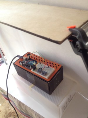
I’m working on a project involving the need to precisely move a tool based on the measured distance to an object. Okay, yeah, it’s a CNC mill. Anyway, I’d heard of time of fight sensors and decided to get one to test out, but also to be thorough I wanted to include other distance sensors as well: a Sharp digital distance sensor as well as a more sophisticated proximity/light sensor. I plugged them all into a breadboard and ran them through their paces, using a frame built from aluminum beams as a way of holding the target materials at a specific height.
Reflected-Light Sensors
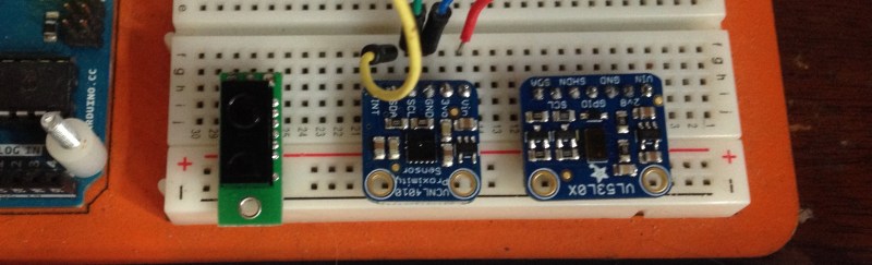
I started with the Sharp GP2Y0D810Z0F digital distance sensor in a Pololu breakout board. It sports sample rate of 400 Hz, which seems more than adequate–I think my project wouldn’t need anything nearly that fast.
It’s basically a small-format replacement for light-based proximity senors, it works the same way, by shining a infrared light and looking for it to bounce back. The down side is that it doesn’t return a distance to the microcontroller–it’s binary, and triggers only when an object enters its field of view between 2 cm and 10 cm. If I were to have this sensor on my toolhead, it could tell if something was blocking the beam, but it couldn’t tell how close the tool was to the material.
Next I checked out the VCN4010 on a breakout board from Adafruit. Like the Sharp it’s more of a proximity sensor than a distance sensor. Adafruit’s testers found it worked best at around 10 mm to around 150 mm, or around 7.5″ and under. One advantage over the Sharp, the VCN4010 has a light sensor built into it. It has some nice features, like the product now supports I2C and interrupts, but I still found it to be not right for the application.
When you use the sensor it returns two numbers: ambient and proximity. The board’s chip has both a light sensor (the ambient number) and an infrared proximity sensor (the other number) and basically pings both sensors continuously and the data is viewable on the serial monitor.
Time of Flight
Forget infrared and parallax, the VL53L0X time-of-flight distance sensor uses an actual laser and measures how long it takes the light to bounce back. Adafruit put it on a board with a level shifter and lux sensor, but you can find breakout boards from eBay or build your own.
It should provide accurate measurements up to 1200 mm (about 4 feet) which is clearly more than I need. On the other end, the VL52L0X isn’t rated to take measurements smaller than 50 mm, or two inches. I don’t think that’s a deal killer. If I have the sensor mounted on the toolhead and shining down, with a chuck and a bit in between, two inches might be alright. Adafruit has another breakout that only measures between 5 mm and 200 mm. To be honest, I’ll never have the sensor in a position where it would need four feet of space to work.
Both time-of-flight sensors have a very tight cone of measurement. Forget an ultrasonic’s tendency to spray sound everywhere, bouncing off of the wrong things and theoretically polluting other ultrasonics. The ToF shoots a little laser beam out and it’s very directional; it senses what is in front of it and nothing else.
On the downside, you also need to point the laser at something that will reflect it properly. I tested out the ToF with a variety of materials, and it definitely likes white and gray. For my project I might need to ensure there’s a swatch of something reflective but not too reflective, at which to aim the laser. Ambient lighting and a reflective white surface improves the accuracy to around +/-3%, while less ideal environments lower it to worse than 10%. For my project, with precision important, 10% could mean the difference between the tool touching the material and it missing completely.
Another downside, and this one is minor, is that you can only connect one sensor to your I2C bus because they have a single hard-coded address. There are hacks to work around this, and there’s even a dedicated I2C address-translation chip that’ll get you out of this particular jam. The good news is that I wasn’t planning to use more than one sensor anyway.
I had a lot of fun testing out the sensors and getting a feel for what their capabilities. And while I am intrigued by the proximity sensing properties of the Sharp and VCN4010, I feel like my application needs more precision. I need to know precisely how far to lower the toolhead, and the ToF’s precision seems perfect for my purposes.


This is an interesting problem that I’ve also looked at solving. Accurate distance measurement in the sub 10-mm range seems hard to accomplish. I’d love to see any solutions.
I´m not sure but maybe you can use multiple mirrors to reflect and increase the time of fly,
A pair of digital calipers? I kid, but I also wonder if you could hack them and get them to output their measurement to an external device. And get them to follow around the thing their measuring mechanically. They’d definitely be accurate.
How do they work, anyway? An optical encoder?
There are several projects here on HaD that have used digital calipers attached to their mills. All the chinese-specials have a serial port
https://hackaday.com/2016/07/24/super-cheap-super-simple-dro
https://hackaday.com/2014/01/19/three-axis-position-indicator-with-digital-calipers/
https://hackaday.com/2010/02/18/lathe-modification/
TGT’s suggestion is well worth looking into. The digital calipers use capacitive sensing which is absolute and I would love to use something like an MPR121 and standard PCB to make a ~200mm closed loop cnc axis.
People have hacked the calipers so just Google to see if it’s something you want to take on.
And if you value your time you could just buy an actual DRO and call it done.
True that it may be better than the calipers but I couldn’t see any easier communication port on the DRO for a closed loop controller. Also, the moving slider of the DROs don’t look that light and mass is preferably kept low for the moving parts of a 3D printer. Obviously I’m taking a punt based on a photo!
If you’re building a custom CNC, why on earth would you go to the trouble of redoing the electronics from the ground up? There’s already the GRBL shield for the Arduino Uno for tethered operation, and the 3d printer standard RAMPS 1.4 package works to if you need untethered for small machines.
Some people just like reinventing the wheel. Why not just order your parts from a company with a professional CNC? Why do anything yourself?
But yeah, I’d probably go with your route myself.
Because RAMPS is rubbish in so many ways.
I heard great things about this one: http://www.escher3d.com/pages/order/products/product1.php
It uses a double IR beam to avoid false readings.
I’ve got that one on my 3D printer, it’s a proximity sensor, max sensing distance is under 3mm.
The I2C addresses on the VL53L0X sensors are not hard-coded. They default to a fixed value when the sensor is reset and can be changed by writing to one of the registers. You can use GPIO pins to reset the sensors so that you can assign one a different address, reset the rest, and then assign the next one a different address. You can read more about that here: https://forum.pololu.com/t/vl53l0x-address-programming/11395
The VL53L0X offers on option to change the i2c address during runtime, but the change won’t be saved.
http://www.st.com/resource/en/application_note/dm00280486.pdf
There is also the option of using capacitive sensors.
In the video below quite a few different sensors were tested for 3d printing.
https://youtu.be/qQu8P0DoUIE
Erm, that seems like a juice advert…
Machinist uses a tool piece called a edge finder for mills to find points down to a hundred mill. Here’s how it works: https://m.youtube.com/watch?v=f0od-cp_9dg
For distance measurement
I’d recomend initially using some inductive proximity sensors (the ones typically with the blue cap)
for the end stop, to get an accurate 0,0 position to start from
There’s a review of different types of sensors here
https://www.youtube.com/watch?v=il9bNWn66BY
Although you will need to opto isolate them since they tend to run on around 12V
For constant measuring along the axis
generally this doesn’t seem to be a done thing at the moment but
1. I’ve seen some people hack an existing pair of digital calipers with a serial interface
as a DRO along the axis.
However the cheaper capacitive ones tend to be more sensitive to crap getting between the caliper
The more expensive inductive ones cost quite a bit and probably not something you want to be hacking
Although I have some ideas for my own to re-create the PCB / layout for an inductive type caliper sensor
2. Another approach is to use one of the TMC stepper drivers like the TMC2660
they have an SPI interface for feedback to indicate if for example they’ve missed a step
I think they might also indicate the amount of force / torque being placed on the motor via stallguard / spi interface
https://www.trinamic.com/products/integrated-circuits/details/tmc2660-pa/
garlicbready I’m interested in your idea for inductive scale/DRO. Anything you can share? Hackaday.io? Thanks.
try googling “Sylvac Inductive Sytem”
http://www.usinages.com/attachments/sylvac-inductive-system-pdf.11864/
Thanks!
Another term I’ve come across (following reading around the Sylvac system) is “linear variable differential transformer” (LVDT) which appears to be the generalised technique employed by Sylvac (who employ a ladder scale, see http://www.holyinstrument.com/service.asp?keyno=12 for some other styles)
For the electronics
I’ve come across 3 types
1. Grbl – This is okay to start with but I’ve had some issues with it
Since it’s a 16bit micro-controller I feel it’s a bit limited for motion control calculations
One problem I had (could just be the version I was using) is that the Z axis would sometimes plow into the board on start
I think it sometimes would ignore the G code to set the machine axis to 0,0,0
Another is that with chillipepr you can’t enable / disable the motor power through the web interface for manually moving the head
2. The next step up is TinyG2 or now renamed to G2Core
they have a dedicated board for it, although at the moment I’m using a Arduino Due with a Radds shield
and custom pinout setup for for the G2Core firmware, with RAPS128 drivers
This feels a bit more reliable that grbl, and uses an ARM processor for calculations
also you can manually enable / disable the motors though the web gui
3. The setup I’m aiming for is using machinekit (originally called linuxcnc I believe)
on a BeagleBone black or green, since it can take advantage of the PRU co-processors on board for motion control.
I think it supports more G codes (the non-standard ones) and can tie in with other stuff
such as a RS485 interface for controlling the spindle speed etc on a VFD
I’m hoping to also use some TMC stepper drivers (since I have nema23 motors) for optimal current and to see if I can feedback into machinekit the torque it’s using
Tangentially, machinekit is a form of LinuxCNC for single board computers. LinuxCNC still exists and is meant for fill up PCs.
In the short bit of time I had learning about manufacturing with CNC equipment, they typically measured each tool length and stored that data in a table, so, you don’t need a sensor to measure distance. The best DIY alternative that I have seen was a simple continuity tester. I wonder if a servo that would *whack* a simple bit of stranded wire on the tool shaft would be enough to do a simple continuity test.
This article and Adafruit state that VL53L0X has a range of 1200mm, while ST datasheet state 200mm??
For sub 10mm measurements, how about hall-effect sensors?
@John Baichtal, could you describe your use case(s) for the sensor? It would help commenters because zeroing (a la bed levelling in 3D printing and part-tool alignment for subtractive processes) has a different set of requirements than a closed loop linear motion system on the axes. Is your sensor for one of those?
How about a camera? I have been wanting to try that myself for sub-millimeter measurements. Something simple like the ubiquitous rpi camera, coupled with a macro lens to get it focused at close range and a few LEDs for illumination, should provide sufficient resolution to measure a 0.2 degree angle, or roughly 0.4 mm at 10 cm range. That’s de-rated a factor of 10 from the raw specs, so performance could most likely be pushed to 3 to 10 times that with careful processing.
This is actually a great idea. A lot of macro lens setups have an obnoxiously-narrow depth of field, but in this case that might be an asset. Assume the workpiece has some surface features, and use a standard “auto-focus” search procedure to find the Z-height you desire. And if the workpiece is too featureless, put a checkerboard sticker on it.
It is a great idea, just wondering if you need a high accuracy sticker!
The VL52L0X datasheet seems to show a range variation window of 1cm at best, within 10cm. Sounds like a tool crash waiting to happen, unless it’s a lot more precise (or at least reproducable) in the real world.
If you need repeatable accuracy, go for absolute optical encoders. Or do the “absolute” part yourself with a dedicated µC and a relative optical encoder – ~€10,– on Ali with 400 ticks / rev – which gives you 1600 / rev with the encoder library. Arduinos seem way too slow for this amount if interrupts, but the ESP handles it well.
Good point about the rotary encoders but they don’t give you the full benefit if there’s mechanical play in the screw/nut interface or screw bearings. That’s where linear encoders have a potential advantage and why they’re an attractive objective.
I apologize for my pedantry, but ‘accuracy’ is a measure of bias and ‘precision’ is a measure of resolution. Please try to use them correctly.
I wonder if it’s possible to measure distance using the return angle of a laser from a reflective target on the workpiece, and a linear CCD array:
https://hackaday.com/2016/07/31/hackaday-prize-entry-a-linear-ccd-breakout/
The resolution of the array might be a limiting factor, but output is analog so with some processing it might be possible to derive sub-pixel resolution. Or maybe a diffraction target would produce a return signal with more detail. Implementation would be similar to the many spectrometer projects featured here on HaD.
Nice idea, and probably a good solution for the original article. Not only is it possible to use the method you suggested, it’s how the Sharp infrared distance sensors work. For example, see “Theory of Operation” on this page:
https://acroname.com/articles/sharp-infrared-ranger-comparison
By building your own, you could very easily add multiple sources to handle a wider set of operating ranges. For a specific project such as a CNC machine, you could mount the laser off to the side so that the beam intersects the moving object at a relatively shallow angle, thus creating a large change in position of the laser spot for a small change in position of the moving object. Or you could mount the laser on the moving object itself. And you don’t even need a linear CCD… you could make some quick prototypes with laser pointers and web cams.
Here’s a bizarre idea: reflect a laser off of multiple mirrors, one set on the frame, the other on the carriage, into a light sensor. As the distance changes, the number of times it bounces changes and the beam will only hit the sensor every so often, so, to make sure that the laser beam always hits the sensor, put the laser on a high precision servo setup. The ToF and angle needed to have it hit the sensor will tell you the distance. Crazy? Dumb? You tell me.
I work in precision motion. I think you’ll be much happier with a rotary encoder because these other sensors are far less accurate and repeatable in terms of their absolute position. Will need to know your motor type – probably DC but possibly stepper. Count the wires to the motor if unsure. DC is usually 2 wires and stepper usually 6 or 8. Will then need appropriate PID motor controller.